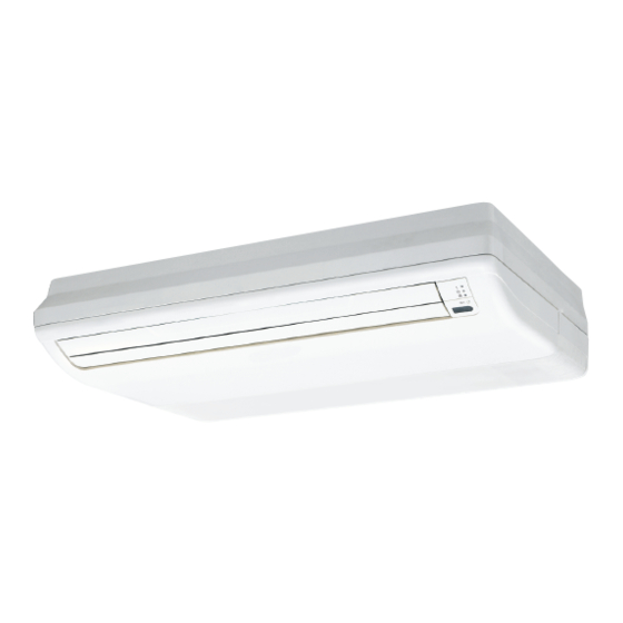
AirStage ABYA12GATH Installatiehandleiding - Pagina 10
Blader online of download pdf Installatiehandleiding voor {categorie_naam} AirStage ABYA12GATH. AirStage ABYA12GATH 16 pagina's.

To peel the fi lm from the lead cable, use a dedicated tool that will not damage the
conductor cable.
When installing a screw on the terminal block, do not cut the cable by overtightening
the screw. On the other hand, an undertightened screw can cause faulty contact, which
will lead to a communication failure.
] 1
6.4. Connection of wiring
(1) Remove the electric component box.
Electric component box
Do not remove the RFM fi xing screws. If the stays are removed, the electric component
box will fall.
If you use as "Floor console", you must remove screws and RFMs (2 position).
When removing the electric component box, remove the clamp from the cables.
After completing the work, fasten the cables as they were originally by installing the clamp.
(2) Pull out the electric component box.
(3) Remove the electric component box cover.
Remove the 3 tapping screws.
Base
Be careful not to pinch the lead cables between the electric component box and
base.
En-9
CAUTION
Electric component box
RFM
CAUTION
Clamp
Cables
Remove the clamp.
Install the clamp.
Electric component box
Electric component box cover
CAUTION
(4) Wiring
* When there is 1 transmission cable or remote controller cable, fasten it the same way as
shown in the fi gure with a cable tie (medium).
When switching the DIP switch (SW1), be sure to turn off the power supply to the
indoor unit. Otherwise, the PC board of the indoor unit may be damaged.
Connect the remote
controller cable
DIP switch
(SW1)
Set the DIP switch
(SW1)
*1: If you connect the remote controller cable to the terminal Y3,
2-wire type remote controller does not work.
] 1
6.5. External input and external output (Optional
parts)
Controller PCB
(CNA03)
Output terminal
(CNB01)
(CNA01)
(1) External input
• Indoor unit can be Operation/Stop, Emergency stop or Forced stop by using indoor unit
PCB CNA01 or CNA02.
• "Operation/Stop" mode, "Emergency stop" mode or "Forced stop" mode can be selected
with function setting of indoor unit.
• Indoor unit can be Forced thermostat off by using indoor unit PCB CNA03 or CNA04.
• A twisted pair cable (22 AWG) should be used. Maximum length of cable is 150 m.
• Use an external input and output cable with appropriate external dimension, depending
on the number of cables to be installed.
• The wire connection should be separate from the power cable line.
Input select
Use either one of these types of terminal according to the application. (Both types of
terminals cannot be used simultaneously.)
CAUTION
Remote controller cable
Y1: Red,
Y2: White,
Y3: Black
X1, X2:
Transmission cable
Cable tie (Medium)
(Accessories)
Cable clamp
L, N: Power supply cable
For 2-wire type
For 3-wire type
Y1:Non-poler
Y1:Red
Y2:Non-poler
Y2:White
Y3:Do not connect *1
Y3:Black
2WIRE
3WIRE
(Factory setting)
(CNA04)
Dry contact terminal
(CNA02)
DIP
switch
(SET 2)
OFF ON
SW1
SW2
SW3
SW4
Apply voltage terminal
