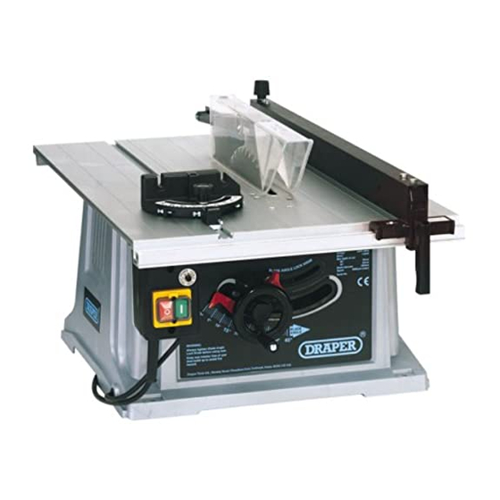
Draper BTS251 Gebruiksaanwijzing - Pagina 9
Blader online of download pdf Gebruiksaanwijzing voor {categorie_naam} Draper BTS251. Draper BTS251 20 pagina's. 10"

ONLY WITH THE POWER SWITCHED OFF
AND THE MACHINE UNPLUGGED SHOULD
ANY ADJUSTMENTS, MAINTENANCE OR
REPAIRS BE CARRIED OUT.
RIP FENCE (FIGS. 4 & 5):
CAUTION:
THE RIP FENCE MUST BE ALIGNED
PARALLEL TO THE BLADE TO MINIMIZE THE
DANGER OF KICK BACK.
Place the rip fence on the side of the table, most
comfortable for your hand orientation. For
example, if you are left handed, the fence would
be secured to the right of the blade.
With the blade guard lifted out of the way, set the
blade to the full height (see page 9) lift the
kickback pawl up to allow the fence to be pushed
flush to the blade. Lock the rear knob ✭✌ and
front locking handle ✮✌ so the fence is securely
held tight against the table. If the fence is not fully
secure, remove the fence and at the rear on
✮✌, under the fence is an adjustment
handle
screw which when moved will allow more grip
with the front handle. On the front fence assembly,
ensure the marker guide is set to zero. If
adjustment is required, loosen screw ✯✌, slide the
plate so zero is correct and then retighten screw
✯✌. Now the fence can be slid to the desired
width of cut and locked in place. To check the
accuracy of the guide, use a metal rule from the
fence and measure the gap between the front of
the blade and also at the back. The measurement
is from the cutting side of the tooth ✰✌. This
measurement should be checked regularly and if
necessary adjusted. When making critical cuts,
always make a test cut from a piece of scrap
timber.
MITRE GAUGE (FIG.6):
The mitre gauge is a guide. The gauge slides
along the two grooves ✱✌ in the table. It should
be checked against the blade using an engineers
square (Draper Stock No.34065) to ensure greater
accuracy. Loosen locking knob ✲✌ and using the
square, set the gauge at 90º to the blade. Now lock
knob ✲✌. Push in rod ✳✌ and adjust quick stop
✴✌ so the set screw touches rod ✳✌, and lock in
place. Carry out the same procedure for the two
45º stops using a protractor (Draper Stock
No.52430) against the blade.
NOTE:
The quick stop is designed to allow quick setting
of the 90º and 45º angles on the gauge. To set
other angles, pull rod ✳✌ out and set manually.
Ensure the locking knob ✲✌ is secured before any
cutting takes place.
ASSEMBLY
✭✌
✯✌
- 8 -
✮✌
✰✌
✲✌
✴✌
✳✌
Fig.4.
Fig.5.
Fig.6.
✱✌
