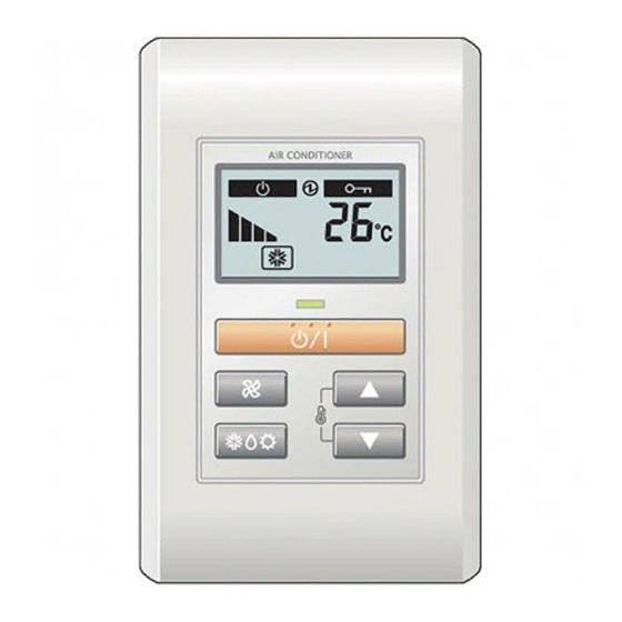
AirStage UTY-RHKY Installatiehandleiding - Pagina 4
Blader online of download pdf Installatiehandleiding voor {categorie_naam} AirStage UTY-RHKY. AirStage UTY-RHKY 8 pagina's. Uty-rhk series
Ook voor AirStage UTY-RHKY: Bedieningshandleiding (2 pagina's), Bedieningshandleiding (20 pagina's)

Fig. 1
3. COM (Black)
2. Signal (White)
1. 12V (Red)
Hole
Cable tie*
* Tighten the cable tie fi rmly so that pulling force does not propagate to the
terminal connection even if force of 30N is applied to the cable.
(3) Cut off the excess cable tie.
(4) Install the rear case to the wall, box, etc., with 2 screws (Fig. 2).
Fig. 2
Box
Insert the upper case fi rmly. If improperly attached, it will cause the upper
case to fall off.
When installing remote control cables,
cover the remote control cables using an
isolation tube or cover at least 1mm thick
minimum to prevent direct contact with
the cables.
Perform functional earthing the remote controller if it
has a functional earthing cable. (UTY-RHKYT)
Insulation*
Remote controller
* Wrap the connector and remote controller cables with vinyl tape
or some other type of insulation as shown in the fi gure.
En-3
7
7
7
1. 12V (Red)
2. Signal (White)
3. COM (Black)
Tightening torque
0.8 to 1.2N • m
(8 to 12 kgf • cm)
Cable tie
Remote Controller Cable
Rear Case
Screws
CAUTION
Cable cover
Epoxy putty
Remote controller
cable
Shield
Connection
Functional earthing
cable (from main unit)
5.2. Setting the DIP switch
Set the remote controller DIP switches. (Fig. 1)
Fig. 1
Unit : mm
DIP switch
5.3. Connection of Remote Controller Cable
When connecting the remote controller cable to the indoor unit, do not
connect it to outdoor unit, power supply cable, or transmission cable
terminal blocks. It may cause a failure.
When switching the DIP switch (SW1), be sure to turn off the power
supply to the indoor unit. Otherwise, the PC board of the indoor unit may
be damaged.
•
There are 2 methods to connect the remote controller cable to the indoor
unit. One is the connection using connecting cable (shipped with the
indoor unit), and the other is the connection the remote controller cable is
connected to the exclusive terminal block of the indoor unit.
•
This is 3WIRE of remote control cables.
•
The factory default setting of the DIP switch (SW1) is "2WIRE"
Using this setting, however, will disable normal operations.
5.3.1. Check whether or not a DIP switch (SW1) is present.
Find the DIP switch (SW1), which switches between 2WIRE and
3WIRE on the indoor unit PC board.
•
If there is no DIP switch (SW1),
proceed to the next step.
ON
OFF
Switch state
NO.
OFF
ON
2
★ Master
Slave
1,3 to 6 ★ Fixed at OFF
CAUTION
DIP switch (SW1)
•
If the DIP switch (SW1) is
present.
Set to "3WIRE" the
DIP switch (SW1)
DIP switch
Detail
Refer to 6. INSTALLA-
TION METHODS.
Cannot be used
(★ Factory setting)
. (Indoor unit)
Indoor unit PC board
2WIRE
3WIRE
SW1
