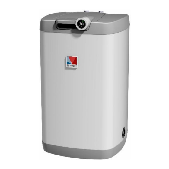
Drazice OKH 160 NTR Bedienings- en installatiehandleiding - Pagina 5
Blader online of download pdf Bedienings- en installatiehandleiding voor {categorie_naam} Drazice OKH 160 NTR. Drazice OKH 160 NTR 12 pagina's. Tank type indirect water heaters
Ook voor Drazice OKH 160 NTR: Bedienings- en installatiehandleiding (14 pagina's), Bedienings- en installatiehandleiding (16 pagina's), Bedienings- en installatiehandleiding (17 pagina's)

Temperature setting
Water temperature is set by turning the thermostat knob. The desired symbol is adjusted against the fixed point on the
control panel.
Lower temperature range
limit (about 5°C)
Fixed point on the control
panel
Anti-freezing temperature
(about 8°C)
Notice: Adjusting the thermostat selector at the left backstop does not mean permanent shutoff of the heating element.
When the heater is in use without blocking the daily rate, we do not recommend the temperature to be set above 65°C.
The maximum value to select is "60".
Limiting the regulation range; locked settings. (Applies to 100 up to 160 l capacities only.)
For various safety reasons (unintentional scalding, preventing children or unauthorised person from handling), the
regulation range can be limited, or the setting on the thermostat blocked.
Limited regulation – pull off the thermostat knob (it will be hard for the first time), and you will find
two 2.15mm cylindrical pins on the back side of the knob
- pull off one pin and insert it to the corresponding hole of the selected maximum temperature.
- put the knob back on (to the stop).
Setting blocked – set the selected temperature
pull off the thermostat knob without changing the setting, there are two pins on the back side of the
knob.
Pull off both of them and fit them to the holes corresponding with the selected temperature so that the
gap between the pins was without a hole, and the position was opposite the set temperature.
6.
PLUMBING FIXTURE
Connection of heaters to plumbing fixtures is illustrated on Fig.1. For potential disconnection of the heater, the
service water inlets and outlets must be provided with screw coupling Js 3/4". If the hot service water distribution is
equipped with circulation circuit, the reverse pipe is connected to the inlet identified as CIRCULATION.
The 100, 125, 160 NTR and 100, 125 NTR / HV types are equipped with a discharge outlet.
Connection of heaters to plumbing fixtures is illustrated on Figures 1 and 2. For potential disconnection
of the heater, the service water inlets and outlets must be provided with screw coupling Js 3/4". Safety valve is mounted
on the cold water inlet identified with a blue ring.
Each hot service water pressure heater must have a safety valve with a membrane spring. Nominal clearance of safety
valves is defined in the ČSN 0 60830 standard. The heaters are not equipped with a safety valve. The safety valve must
be easily accessible, as close to the heater as possible. The input pipes must have at least the same clearance as the
safety valve. The safety valve is placed high enough to secure dripping water drain by gravity. We recommend
mounting the safety valve onto a branch pipe. This allows easier exchange without having to drain the water from the
heater. Safety valves with fixed pressure settings from the manufacturer are used for the assembly. Starting pressure of
Regulation limited
Setting blocked
5
Upper temperature range
limit (about 74°C)
"Ideal" temperature
(about 60°C)
