CommScope 2064184-1 Instructieblad - Pagina 4
Blader online of download pdf Instructieblad voor {categorie_naam} CommScope 2064184-1. CommScope 2064184-1 17 pagina's. Fiber optic connector kits
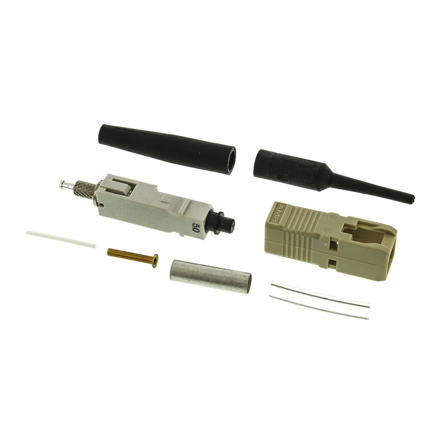
250-m m Coated Fiber
5.2.
Kit Components Required
(Discard Other Components)
Connector
Assembly
Termination
Cover
Connector
Housing
Connector kit is shipped with these installed onto connector
assembly. Keep them in place until ready for assembly.
A. Preparing 250-mm Coated Fiber
1. Slide the bare bu er boot (small diameter end
rst) over the ber. See Figure 2, Detail A.
2. Remove the plunger dust cap from the
connector assembly, and discard.
3. Insert the small (white) tubing into the plunger of
the connector assembly until the tubing bottoms.
See Figure 2, Detail A.
4. Push the connector assembly into the holder of
the cable holder assembly with the termination
cover facing outward. See Figure 2, Detail B. Make
sure that the connector butts against the lip on the
arm of the cable holder assembly. Slide the ber
into the channel marked "BUFFER". Make sure
that the tip of the ber butts against the end of the
channel.
5. Mark the ber at each cross--slot of the channel.
See Figure 2, Detail B. Then, remove the ber
from the cable holder assembly.
6. Using the strip tool, strip the ber to the rst
mark. It is recommended holding the strip tool at
an angle to the ber and stripping the ber in three
sections. See Figure 2, Detail C. Clean the ber
with an alcohol ber wipe to remove the ber bu er
residue.
Before using the strip tool, make sure that the "V"
CAUTION
opening is clean; otherwise the ber could break.
!
Only use isopropyl alcohol on the tool.
4 of 17
Plunger
Dust Cap
Bare Bu er
Boot
Small
Tubing
(Figure 2)
B. Cleaving
(Figure 3)
1. Open the ber clamp of the ber optic cleaver.
Press the button, and slide the carriage back
(toward the ber clamp). Then move the ber slide
back until it stops.
2. Place the stripped ber into the slot so that the
end of the bu er is at the 8--mm marking. See
Figure 3, Detail A.
3. While applying pressure on the bu er, carefully
slide the ber slide forward (toward the carriage)
until it stops. See Figure 3, Detail B.
4. Gently close the ber clamp, and slide the
carriage forward. DO NOT touch the button while
sliding the carriage. See Figure 3, Detail C.
5. Open the ber clamp, and move the ber slide
back until it stops.
6. Remove the cleaved ber, and properly dispose
of the scrap ber.
CAUTION
DO NOT attempt to clean the ber after it has
been cleaved.
!
C. Crimping
(Figures 4 and 5)
1. Open the cable clamp of the cable holder
assembly, and position the ber (with the cleaved
end facing the connector) inside the clamp. Move
the ber so that the end of the ber is even with
the front of the arm of the cable holder assembly,
and holding the ber in place, close the clamp. See
Figure 4, Detail A.
2. Carefully insert the ber into the plunger of the
connector assembly until the ber bottoms against
the internal ber. Make sure that the remaining
mark on the ber enters the plunger. The resultant
bend in the ber should hold the ber against the
internal ber. See Figure 4, Detail B.
Also, the ber coating must enter the small tubing
that was installed in Step 3 of Paragraph 5.2.A.
Make sure that the start of the ber coating is not
caught on the entry of the small tubing.
It is important that the ber bottoms against, and
NOTE
remains against, the internal ber. If the mark
i
does not enter the plunger or if the ber does not
seem to bottom against the internal ber, the
ber may be caught on internal guides. Rotating
the connector and backing the ber out a small
amount and re--entering may help. However, if
the mark will not enter the plunger, the ber must
be re--stripped.
Make sure that the ber does not pull rearward
from the contact with the internal ber during the
crimping operation.
408- 4471
Rev N