CommScope 2064184-1 Instructieblad - Pagina 8
Blader online of download pdf Instructieblad voor {categorie_naam} CommScope 2064184-1. CommScope 2064184-1 17 pagina's. Fiber optic connector kits
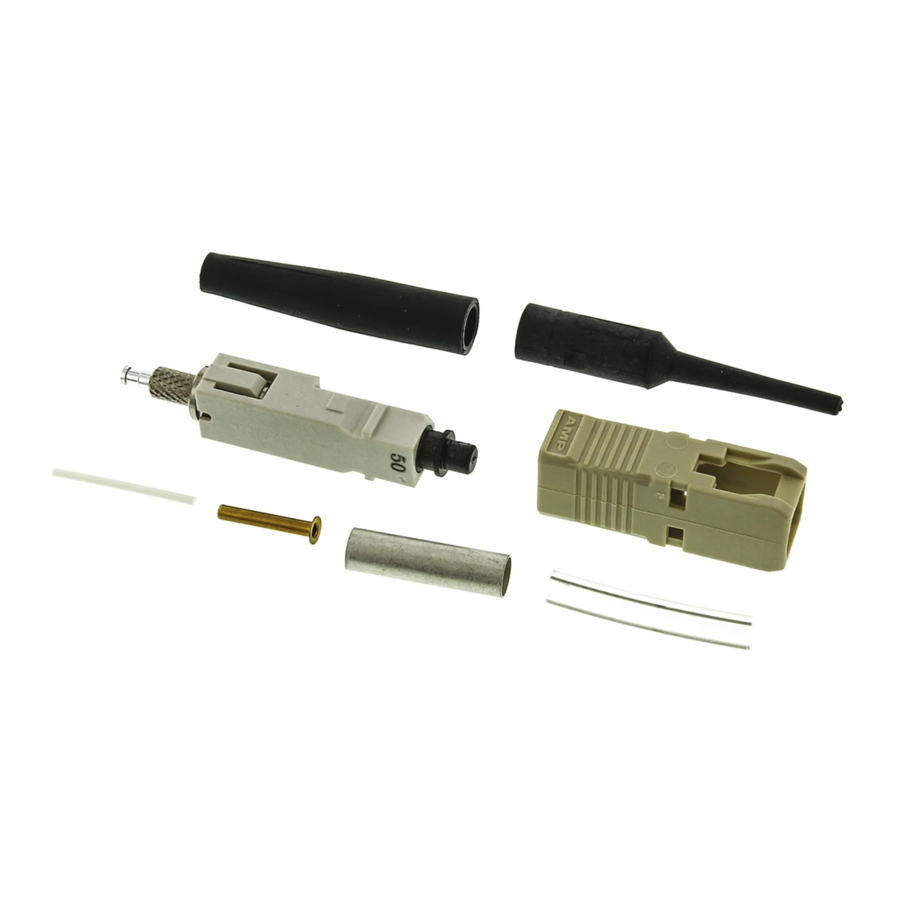
2.5- to 3.0- mm Loose Jacketed Cable
5.3.
Kit Components Required
(Discard Other Components)
Connector
Assembly
Termination
Cover
Connector
Housing
Connector kit is shipped with these installed onto connector
assembly. Keep them in place until ready for assembly.
A. Preparing 2.5- to 3.0- mm Loose Jacketed Cable
(Figures 6 and 7)
1. Slide the strain relief (small diameter end rst)
over the cable. See Figure 6, Detail A.
2. Remove the plunger dust cap from the
connector assembly, and discard.
3. Push the connector assembly into the holder of
the cable holder assembly with the termination
cover facing outward. See Figure 6, Detail B. Make
sure that the connector is sitting at against the
arm of the cable holder assembly. Slide the cable
into the channel marked "CABLE." Make sure that
the tip of the jacket butts against the end of the
channel.
4. Mark the cable at the right--most cross--slot of
the channel. See Figure 6, Detail B. Then, remove
the cable from the cable holder assembly.
5. Using the strip tool, cut through the jacket at the
mark. See Figure 6, Detail C.
6. Remove the jacket segment, gather the strength
members in a bundle, and fold them back along
the jacket. See Figure 6, Detail D.
7. Slide the crimp eyelet over the bu er and onto
the strength members to hold them in place. Slide
the inner eyelet, non-- anged end rst, onto the
bu er. Push the inner eyelet under the strength
members until the face is ush with the front of the
crimp eyelet. See Figure 7, Detail B.
8 of 17
Plunger
Dust Cap
Strain
Relief
Inner
Eyelet
Crimp
Eyelet
8. Slide the bu er into the channel marked
"BUFFER" on the cable holder assembly. Make
sure that the tip of the bu er butts against the end
of the channel. See Figure 7, Detail C.
9. Mark the bu er at each cross--slot of the
channel and at the right end of the channel (total of
three marks). See Figure 7, Detail C. Remove the
bu er from the cable holder assembly.
10. Using the strip tool, strip the bu er to the rst
mark. It is recommended holding the strip tool at
an angle to the bu er and stripping the bu er in
three sections. See Figure 7, Detail D. Clean the
ber with an alcohol ber wipe to remove ber
coating residue.
Before using the strip tool, make sure that the "V"
CAUTION
opening is clean; otherwise the ber could break.
!
Only use isopropyl alcohol on the tool.
B. Cleaving
(Figure 8)
1. Open the ber clamp of the ber optic cleaver.
Press the button, and slide the carriage back
(toward the ber clamp). Then move the ber slide
back until it stops.
2. Place the stripped bu er into the slot so that the
end of the ber is at the 8--mm marking. See
Figure 8, Detail A.
3. While applying pressure on the ber, carefully
slide the ber slide forward (toward the carriage)
until it stops. See Figure 8, Detail B.
4. Gently close the ber clamp, and slide the
carriage forward. DO NOT touch the button while
sliding the carriage. See Figure 8, Detail C.
5. Open the ber clamp, and move the ber slide
back until it stops.
6. Remove the cleaved ber, and properly dispose
of the scrap ber.
DO NOT attempt to clean the ber after it has
CAUTION
been cleaved.
!
C. Crimping
(Figures 9, 10, and 11)
Only use Die Set 492783- - 1 to terminate 2.5- - to
3.0- - mm loose jacketed cable.
1. Open the cable clamp of the cable holder
assembly, and position the bu er (with the cleaved
end facing the connector) inside the clamp. Move
the bu er so that the end of the ber is even with
the front of the arm of the cable holder assembly,
and holding the bu er in place, close the clamp.
See Figure 9, Detail A.
408- 4471
Rev N