ATI Technologies BL60121 Gebruiksaanwijzing - Pagina 5
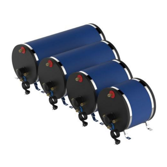
Blader online of download pdf Gebruiksaanwijzing voor {categorie_naam} ATI Technologies BL60121. ATI Technologies BL60121 8 pagina's. Marine water heater with dual heating as standard: electrical heating and indirect heating

INSTALLATION
Connections (FIG_8-1):
1. cold water inlet (1/2 ")
2. hot water outlet (1/2 ")
3. Water supply to the engine cooling circuit (1/2 ")
4. return water from the engine cooling circuit (1/2 ")
MAX TEMPERATURE OF RETURN WATER FROM THE ENGINE COOLING CIRCUIT : 65 °C
It is recommended to insulate the hot water pipes in order to avoid unnecessary waste of energy.
The device is equipped with pressure relief valve (calibration: 800 kpa) : it protects the tank from possible excessive
pressures caused by the expansion of water during heating.
Upon the occurrence of this situation, the water is discharged through the outlet of which is equipped with the valve (S -
FIG_8-1). Caution: Connect the water drain valve to a rubber tube
PIPE CONNECTED TO DISCHARGE VALVE MUST NOT BE SEALED OR LOCKED, MUST BE
INSTALLED WITH A CONSTANT INCLINE DOWN AND PROTECTED BY ICE.
IT MUST NOT BE CONNECTED TO A COCK AND MUST BE KEPT CONSTANTLY FREE OF
OBSTRUCTION
9. ELECTRICAL CONNECTIONS
The heater be connected to a single-phase power supply (please pay attention to connect the correct voltage according to
the data present on the label) and to an effective ground connection.
CAUTION: BEFORE MAKING THE CONNECTION, MAKE SURE THE POWER IS COMPLETELY
DISCONNECTED. THE BUILDER DOES NOT ACCEPT RESPONSIBILITY FOR POSSIBLE DAMAGE
CAUSED BY FAILURE OF THE APPLIANCE BE GROUNDED
The apparatus is equipped with a power cord with plug. Plug the power cord in accordance with the wiring regulations in force
in the country where the equipment is installed.
Should it is not necessary to use the safety plug is possible to cut the power cord and connect it to a different plug or directly
to the supply connection (operation that can be performed only by authorized personnel).
If the supply cord is damaged, it must be replaced by the manufacturer, its service agent or similarly qualified persons in
order to avoid a hazard
In case of replacement of the power cord, use only a cable with the same characteristics: H05 VV-F - 3G 1.5 mm
Be careful in properly connect the polarities (FIG_9-1):
The electrical system a bipolar switch must be installed to turn on and off the device and a fuse of suitable rating. The
connections to the mains must be made in accordance with the national standards of electrical installations.
WARNING: CONNECT THE POWER TO THE ELECTRIC HEATER ONLY WHEN THE TANK IS FULL OF
WATER. THE HEATING ELEMENT IS NOT SUITABLE FOR OPERATION DRY
10.SETTING THE WATER TEMPERATURE
On the electrical resistance there is a thermostat, which interrupts the power supply when the preset temperature is reached.
Setting the temperature (T - FIG_09-1): it is possible to adjust the hot water temperature between 0 ° C and 60 ° C, according
to the user's needs. The thermostat regulates the water temperature in the operation exclusively with electrical resistance.
WARNING: BEFORE WORKING ON THE THERMOSTAT, MAKE SURE THE POWER IS COMPLETELY
DISCONNECTED
L
phase (brown wire)
Plant scheme (FIG_8-2):
A. sanitary water tank
B. pump
C. pressure reducer
D. non-return valve
E. water heaters
F. engine cooling circuit
G. point of hot / cold water use (shower, sink, etc ..)
N
neutral (blue wire)
ENGLISH
p. 3/4
2
