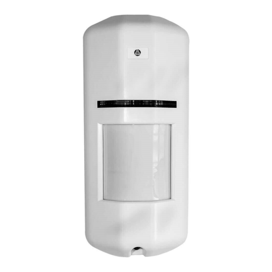
Aleph XC-1XT Installatie-instructies
Blader online of download pdf Installatie-instructies voor {categorie_naam} Aleph XC-1XT. Aleph XC-1XT 2 pagina's. Outdoor dual technology detector animal immune (80 lbs.)

OUTDOOR DUAL TECHNOLOGY DETECTOR
XC-1XT
1. SPECIFICATIONS
Power Requirement
Current Draw
PIR Detector
PIR Detection Range
PIR Sensitivity Adjustment
PIR Pulse Count
MW Detector
MW Range Adjustment
MW Detection Range
MW Pulse Count
Warm-up Period
Alarm Period
Alarm Display
PIR Detection Display
MW Detection Display
Relay Output
Tamper Contact
Operating Temperature
Environment Humidity
Dimensions(H × W × D)
Weight
We may change specification and design without prior notice as part of its
continuing program of product improvement.
2. DETECTION PATTERN
TOP VIEW
7. INSTALLATION HINTS
Do not install towards a
driveway and a place with much
traffic, etc.
ANIMAL Immune (80 lbs.)
9.5 to 16VDC (Normal 12VDC)
35mA max.
Dual-Element
Standard (Animal immune) range lens
Long range lens (option)
Selectable (60 or 80 or 100 or 120%)
Selectable (2 or 4 pulses)
MIC Module (10.525GHz)
Volume Adjustment
20ft to 66ft (6m to 20m)
2 pulses
±
50
15 sec
±
2
0.4 sec
Red LED monitor (ON/OFF selectable)
Green LED ON
Orange LED ON
2C Contact (N.C/N.O)
30VDC 0.35A max.
N.C dry contact 30VDC 0.5A max.
− 4
F to + 122 ゚ F ( − 20
to + 50
゚
℃
95% max.
×
×
6.3in.
2.76in.
1.73in.
×
×
(160mm
70mm
43.9mm)
6.3oz(180g)
SIDE VIEW
MW DETECTION AREA
Do not limit a desired detection
zone by interference of car,
screen, potted plants, etc.
INSTALLATION INSTRUCTIONS
3. DESCRIPTION
PRINTED CIRCUIT BOARD
PIR LED
LOCKING SCREW
ALARM LED
MW RANGE
ADJUSTMENT
TAMPER SWITCH
4. DIMENSIONS
℃
)
2.76 (70)
5. MODE SWITCH
PIR SENSITIVITY
ADJUSTMENT
PIR SENSITIVITY
ADJUSTMENT
PIR PULSE COUNT 2
LED ON
DUAL MODE
(PIR & MW)
6. MW Range Adjustment
MW range adjustment is provided allowing
use in difficult environments.
MAX:Increases
ft(m)
MIN :Decreases
Mount the unit only on a solid
locatiom or surface.
MW DETECTOR
MW LED
MODE SWITCH
PIR DETECTOR
RELAY
TERMINAL
Mounting hole
1.73 (43.9)
inches ( mm )
120% 100% 80%
60%
4
OFF
PIR MODE
(PIR only)
MIN
MAX
Y ft ( X m)
Y: 6.6 ∼ 8.2 ft
X: 2.0 ∼ 2.5 m
Unit installed height should be
Y ft (X m) from floor so that the
full coverage could be achieved.
640-43575
