Carotron C14521-001 Gebruiksaanwijzing - Pagina 5
Blader online of download pdf Gebruiksaanwijzing voor {categorie_naam} Carotron C14521-001. Carotron C14521-001 18 pagina's. Ethernet/ip
3 3 3 3
Installation
3.1 Physical Installation
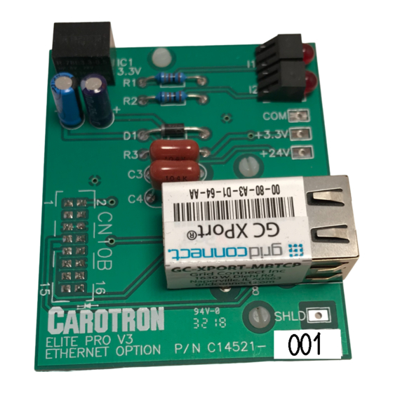
The C14521-001 option card installs onto the control board of the Elite
1. Remove all power from the Elite
power.
2. Align the option card connector CN10B with the control board connector CN10.
Ensure the 3 support standoffs are aligned with the holes on the control board.
3. Press down on the option card ensuring all 3 standoffs are seated fully.
4. Connect your Ethernet cable to the option card.
3.2 Wiring Guidelines
To prevent electrical interference and to minimize start-up problems, adhere to the
following guidelines:
Use fully insulated and shielded cable for all signal wiring. The shield should be
connected to circuit common at one end only. The other end of the shield should be
clipped and insulated to prevent the possibility of accidental grounding.
Signal level wiring such as listed above should be routed separately from high level
power wiring (such as the A.C. line, motor, operator control, and relay control wiring).
When these two types of wire must cross, they should cross at right angles to each
other.
Any relay, contactor, starter, solenoid or other electro-mechanical device located in close
proximity to the C14521-001 should have a transient suppression device such as an
MOV or R-C snubber connected in parallel with its coil. The suppressor should have
short leads and be connected as close to the coil as possible.
®
Pro V3 drive. This includes main and control
®
Pro V3 drive.
5