Compact C3048 Gebruikers- en installatiehandleiding - Pagina 5
Blader online of download pdf Gebruikers- en installatiehandleiding voor {categorie_naam} Compact C3048. Compact C3048 14 pagina's. Sinewave inverter, battery charger

Studer Solartechnik
Stage 2:- Connecting the 230Vac appliance (AC Output)
Caution
Ensure that the inverter is OFF prior to connecting this cable.
The 230Vac consumer device (load) must be connected to the screw terminals marked 'AC OUTPUT'.
For this use a 3-core mains cable with a minimum cross sectional area of 2.5mm
Stage 3:- Connecting the 230Vac Input Supply (AC Input)
Caution
Ensure that the AC source is disconnected prior to connecting this cable.
The 230Vac supply from a network or generator must be connected to the screw terminals marked 'AC
INPUT'. For this use a 3-core mains cable with a minimum cross sectional area of 2.5mm
Stage 4 :- Connecting to the Auxiliary Contacts
These three terminals are potential free (volt free) change-over relay switch contacts.
The maximum permitted current and voltage for these contacts is 16A/250Vac. The schematic of these
switch contacts is clearly marked above each of the terminals. This schematic illustrates the relay in the
non-active state. LED 5* on the front of the unit will illuminate if this relay is Active.
The relay can be programmed to switch due to various conditions (Programming mentioned later). It is
factory set to operate during the following conditions:-
The relay can also be manually switched ON/OFF using button 21* on the front of the unit.
*
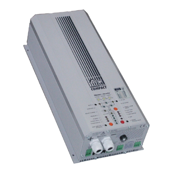
Please refer to the 'Display and Operating Panel' photograph on page 6
Stage 5:- Connecting the optional Remote Control (if required)
The remote control (RCC01) is connected by simply pushing the RJ11/8 connector located on the end of
the cable supplied into the socket marked 'Remote Control' on the end of the COMPACT. The other end
of the cable plugs into the RJ11/8 connector on the Remote Control.
The remote control is supplied with a 20m cable. This cable can be replaced with a standard RJ11/8 up
to a maximum length of 40metres.
Stage 6:- Connecting the Temperature Sensor (if required)
The temperature sensor (CT-35) is connected by simply pushing the RJ11/6 connector located on the
end of the cable supplied into the socket marked 'Temp' on the end of the COMPACT. The sensor must
then be securely fastened to the wall of the battery or close to it. The temperature sensor cable must
not be tied to the battery leads or laid into part of a wiring loom.
Connections marked as follows:-
Connections marked as follows:-
1. Over temperature
2. Overload
3. Over-voltage or Under-voltage on the batteries
4. If the COMPACT has been turned OFF manually or with a fault.
Sinewave Inverter, Battery Charger
'N'
-
'PE'
-
'L'
-
'N'
-
'PE'
-
'L'
-
- 5 -
2
.
Neutral (blue)
Earth (green/yellow)
Live (brown)
2
.
Neutral (blue)
Earth (green/yellow)
Live (brown)
