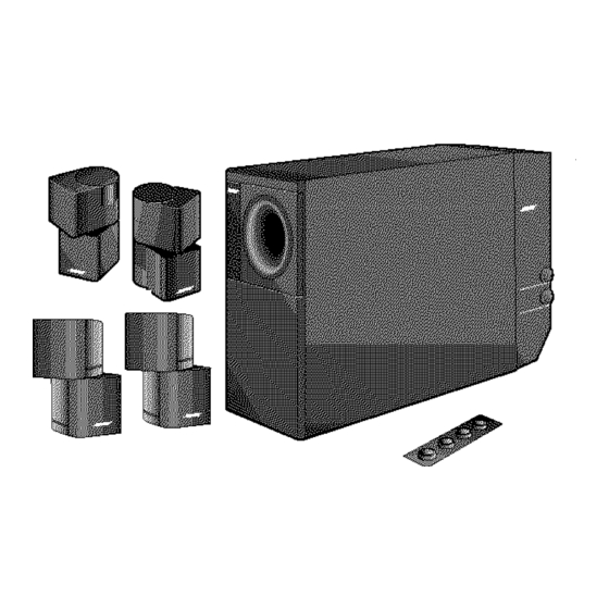
Bose Acoustimass 5 Gebruikershandleiding - Pagina 9
Blader online of download pdf Gebruikershandleiding voor {categorie_naam} Bose Acoustimass 5. Bose Acoustimass 5 22 pagina's. Powered speaker system
Ook voor Bose Acoustimass 5: Gebruikershandleiding (9 pagina's), Gebruikershandleiding (22 pagina's), Gebruikershandleiding (16 pagina's)

Connect
the speakers
and the Acoustimass
_ module
Connecting
the Acoustimass
20 Jewel
Cube _ speakers
to the
Acoustimass
module
1. Insert the connector of each speaker cable fully into the jack on the rear of each speaker
(Figure 5). Match the ridge of the connector to the notch at the top of the jack.
2. Connect each 20-foot (6.1 m) cable to the corresponding left or right green jack on the
Acoustimass module. Speaker cables have green connectors at one end, with L (left) and
R (right) molded into the connectors.
To extend the length of speaker cable, you will need a 30-foot extension cable. To order this
part, please call Bose_'customer service (request PN 186445-1 black; PN 186445-2 white).
Or, splice in 18-gauge (.75 mm 2)or thicker cord (connecting + to + and -to -). To purchase
extension wire, see your dealer, electronics store, or call Bosecustomer
service.
Figure
5
Speaker cable connec_ns
the Jewel Cube speaker array
Figure
6
Speaker cable connections
the cube speaker array
Connecting
the Acoustimass
5 cube
speaker
arrays
to the
Acoustimass
module
Each speaker cable contains two wires. The wire marked with a red collar is positive (+) and
the ribbed one is negative (-). These wires match the positive (red) and negative (black)
terminals on the back of each speaker. To extend the length of speaker cable, you will need a
30-foot extension cable. To purchase this cable see dealer, electronics store, or call Bose
customer service. To order this part from Bose, please call Bose customer service (request
PN 186445-1 black; PN 186445-2 white). Or, splice in 18-gauge (.75 mm 2)or thicker cord
(connecting + to + and -to -).
1.
Match the correct cable to the corresponding speaker location.
• Speaker cables have blue connectors at one end, with L and R molded into the
connectors.
• The red collars on the + wire are labeled LEFT and RIGHT.
2,
Connect the wire end of one speaker cable to the terminals on the rear of the matching
cube speaker array.
a. Press the terminal tab on the back of the cube array to insert the marked wire into the
red terminal and the plain wire into the black terminal. Release the tab to secure the
wire.
b. Repeat this step for each of the cube speaker arrays (see Figure 6).
3. Connect each cable to the corresponding left or right blue jack on the Acoustimass
module.
CAUTlON:
Make sure no strands of wire from any terminat touch any other terminaL Bridged
wires create short oircuits that affect proper operation of your system.
AM262838
00 !Zpdf
December20,
2001
7
