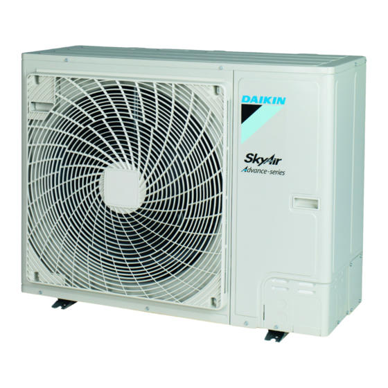
Daikin Sky Air Advance RZA200D7Y1B Installatiehandleiding - Pagina 7
Blader online of download pdf Installatiehandleiding voor {categorie_naam} Daikin Sky Air Advance RZA200D7Y1B. Daikin Sky Air Advance RZA200D7Y1B 20 pagina's.

4.1.2
To install the outdoor unit
4.1.3
To provide drainage
INFORMATION
If necessary, you can use a drain pan (field supply) to
prevent drain water from dripping.
NOTICE
If the unit CANNOT be installed fully level, always make
sure that the inclination is towards the backside of the unit.
This is required to guarantee proper drainage.
NOTICE
If drain holes of the outdoor unit are covered by a mounting
base or by floor surface, raise the unit to provide a free
space of more than 150 mm under the outdoor unit.
Drain holes (dimensions in mm)
A
171
758
B
43
48
107
288
451
613
776
A
Discharge side
B
Distance between anchor points
C
Bottom frame
D
Drain holes
E
Knockout hole for snow
Snow
In regions with snowfall, snow might build up and freeze between the
heat exchanger and the casing of the unit. This might decrease the
operating efficiency.
RZA200+250D7Y1B
Sky Air Advance-series
4P573384-1 – 2019.04
4× M12
171
C
D
=
E
INFORMATION
We suggest to install the optional bottom plate heater
(EKBPH250D7) when the unit is installed in cold climates.
4.1.4
To prevent the outdoor unit from falling
over
In case the unit is installed in places where strong wind can tilt the
unit, take following measure:
1 Prepare 2 cables as indicated in the following illustration (field
supply).
2 Place the 2 cables over the outdoor unit.
3 Insert a rubber sheet between the cables and the outdoor unit
to prevent the cables from scratching the paint (field supply).
4 Attach the ends of the cables and tighten them.
4.2
Connecting the refrigerant piping
DANGER: RISK OF BURNING
4.2.1
To connect the refrigerant piping to the
outdoor unit
▪ Piping length. Keep field piping as short as possible.
▪ Piping protection. Protect the field piping against physical
damage.
1 Do the following:
▪ Remove the service cover (a) with screw (b).
▪ Remove the piping intake plate (c) with screws (d).
a
c
b
d d
2 Choose a piping route (a, b, c or d).
c
a
b
d
a
Front
b
Side
4 Installation
Installation manual
7
