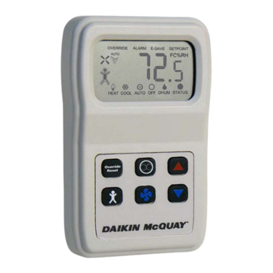
Daikin McQuay 910113679 Installatie- en onderhoudsgegevens - Pagina 7
Blader online of download pdf Installatie- en onderhoudsgegevens voor {categorie_naam} Daikin McQuay 910113679. Daikin McQuay 910113679 16 pagina's. Digitally adjustable display sensor for water source heat pumps smartsource gs series; smartsource gt series; with microtech iii controls enfinity cch series; enfinity ccw series; enfinity vfc series; enfinity vfw series; enfinity lvc series; enfinity lvw

Mounting
Location
Avoid mounting on outside walls or in direct sunlight.
Junction Box, (J-Box)
1. Pull the wire through the wall and out of the junction box,
leaving about six inches free.
2. Pull the wire through the hole in the base plate.
3. Secure the back plate to the box using the #6-32 × 1/2
inch mounting screws provided.
4. Screw the plate firmly to the wall so the foam plate
backing is compressed about 50%.
5. Terminate the unit according to the guidelines in the
Termination section.
6. Attach Cover by latching it to the top of the base, rotating
it down and snapping into place.
7. Secure the cover by backing out the lock-down screws
using a 1/16" Allen wrench until it is flush with the bottom
of the cover.
Figure 6: Junction box mounting (hardware is provided
for both junction box and drywall installation.)
Mounting
base plate
Cover lockdown screws 1/16" allen
Drywall Mounting
1. Place the base plate against the wall where you want to
mount the sensor.
2. Mark out the two mounting holes where the unit will be
attached to the wall. Drill a 3/16" hole in the center of
each mounting hole and insert a drywall anchor into the
holes.
3. Drill one 1/2" hole in the middle of the marked wiring
through hole area.
4. Pull the wire through the wall and out the 1/2" hole,
leaving about six inches free.
5. Pull the wire through the hole in the base plate.
6. Secure the base to the drywall anchors using the #6 × 1"
mounting screws provided.
7. Screw the plate firmly to the wall so the foam plate
backing is compressed about 50%.
8. Terminate the unit according to the guidelines in the
Termination section.
9. Attach cover by latching it to the top of the base, rotating
it down and snapping it into place.
10. Secure the cover by backing out the lock-down screws
using a 1/16" Allen wrench until it is flush with the sides
of the cover
Note: in any wall-mount application, the wall temperature
and the temperature of the air within the wall cavity
can cause erroneous readings.
The mixing of room air and air from within the wall
cavity can lead to condensation, erroneous readings
and sensor failure. To prevent these conditions, Daikin
McQuay recommends sealing the conduit leading to
the junction box with fiberglass.
Maintenance
Wipe the display as needed with a damp water only cotton
cloth. Do not use any type of cleaner as it may damage the
buttons or scratch the display. Do not paint.
Terminal Descriptions
R ........... 15 to 28VAC* (AC requires separate shielded wire)
(Shield terminated at power source only)
DH ........Dehumidification Contact (Triac from R to DH
@170mA, WHSP Only).
U ...........Unoccupied Contact. (Terminal grounded when in
Unoccupied, VDC only).
E ........... System "Off" Indication. (Terminal grounded when
in System "Off" mode, VDC only).
1............ Status Indicator Input from the MicoTech III Smart-
Source Unit Controller. (5VDC).
2............ Output Signal, and Fan Mode System (0 to 5VDC).
Output Signal, System Mode Select for FCU only, (0
to 5VDC).
3............ Output Signal, Setpoint Adjust from 55º to 95˚F (de-
fault) or ±5º Configurable. (0 to 5VDC) See Setpoint
Analog Range Tolerances.
4............ Output Signal, Room Temp Thermistor Sensor. (10K
ATP Z curve, 10K-2).
5............ Ground or Neutral* (AC requires separate shielded
wire). Common Reference for All Signal Terminals.
6............ Output Signal, Fan Speed Select for FCU only. (0 to
5VDC). Terminal 6 not used for WSHP units.
Note: * The AC power wiring at terminals [R] & [5] should
be run in a separate twisted shielded pair to avoid
possible fluctuating and inaccurate signal levels
induced into the other sensor signal wires.
This sensor AC power can be run in the same conduit
with the sensor signal wire as long as it's run in
twisted, shielded pair and terminated properly.
See Table
3.
IM 1171-3 / Page 7 of 16
