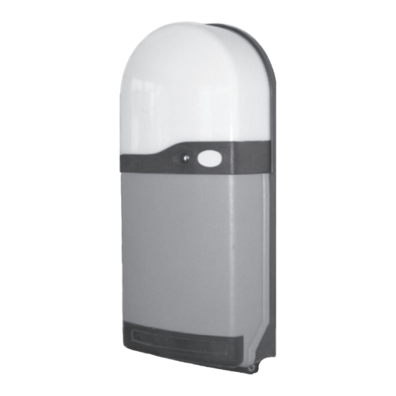
Ansa RS-1 Handleiding voor installatie en gebruik - Pagina 11
Blader online of download pdf Handleiding voor installatie en gebruik voor {categorie_naam} Ansa RS-1. Ansa RS-1 12 pagina's. Ansa roller door remote control unit

- 1. Table of Contents
- 2. General Description
- 3. General Operation
- 4. Multi Channel Keyfobs
- 5. Fitting the RS-1 Control Unit
- 6. Electrical Connections
- 7. Photoelectric Cell Safety System (Optional)
- 8. Light Grid Safety System (Optional)
- 9. Alarm System (Optional)
- 9. Figure 16
- 9. Commissioning
- 9. Adding/Deleting Transmitters & Wireless Access Controls
- 9. Dip Switch Options & Special Settings
- 9. Technical Specifications
16 Problem Solving Guide
LED Signal
Door Status
LED On
Operational
LED Off
Door is not operational
LED On
Door is not operational
LED flashing
Door opens but
rapidly
will not close
(doors with photocell
safety system)
LED flashing
Door opens but
rapidly
will not close
(doors with Light Grid
Safety System)
LED On
Door is operational but
sometimes re-opens
when closing
LED flashing
Door is not operational
slowly every
2 seconds
LED On
Door is operational but
has reduced range from
keyfob transmitter
Page 10
Cause
No fault
Power supply fault
Fuse in plug has blown
PCB fuses have blown
Other fault
Possible Motor Fault
Motor thermal trip
has activated
Motor limit switches
need to be set
Possible motor fault
has developed
Possible Safety System
Fault
Photoelectric cell (PEC)
beam is obstructed
Green PEC LED is ON
& yellow PEC LED is
off or flashing
Light grid beam(s)
obstruction
Green grid transmitter
track LED is ON
Yellow grid receiver
track LED is OFF
Photoelectric cell or
Safety grid problem
Stop circuit is activated
Additional push button
control is of the wrong
type or has a wiring fault
RS1 control button is
faulty
Battery in transmitter
is weak - keyfob LED is
dim
Aerial has not been fitted
to RS1 control unit
Solution
Door in stand-by mode
Test mains power supply and switch on or Reset circuit breaker
Replace 5amp fuse in 3 pin plug (or spur unit)
Replace PCB main fuse (coloured white) 6.3amp 5mmx20mm
Replace PCB control fuse (clear) 500ma 5mmx20mm
(note: spare fuses are fitted to RS1 cover - See fig. 5)
Possible PCB failure - Contact your Installer
Allow door motor to cool for approximately 20 minutes
before attempting to operate the door
Adjust or set motor limit switches in accordance with door
manufacturers instructions
Close door with manual override. Switch on dip switch number3.
Try to operate door using RS1 control button. A possible motor
fault is indicated if the door fails to operate but the door open
and door close LEDs illuminate. If so - Contact your Installer
Remove any obstacles in the doorway
Ensure the Photoelectric cell and Reflector are clean
Check alignment of the Photoelectric cell
* If no fault is found - Contact your Installer - Door can be
closed using 'hold-to-run' mode (see Fig. 2.4, page 5)
Remove any obstacles in the doorway
Carefully clean all optical ayes on both the
transmitter and receiver safety grid tracks
Check alignment of safety grid tracks alignment
* If no fault is found - Contact your Installer - Door can be
closed using 'hold-to-run' mode (see Fig. 2.4, page 5)
Check that Photoelectric cell brackets are secure
Check that the Safety grid tracks are secure
Ensure the Roller Door Curtain is not deflecting due to the
effects of wind loading and space the safety grid tracks or
photocell sensor further away from the door guides if necessary
RS1 (status) LED should be in green. If it is red - check that the
PCB link is (or Stop push button) connected to terminals COM
and STP is correctly installed
Do not connect push buttons having neon illumination
Push buttons should be 'push to make' type
Check for short circuit in push button or wiring
Check RS1 control button operation.
Button should click when pressed
Renew keyfob transmitter battery
Install steel wire aerial (see 4.7, page 4 and Fig. 3, page 5)
