Foxconn R40-H1 Specificatie
Blader online of download pdf Specificatie voor {categorie_naam} Foxconn R40-H1. Foxconn R40-H1 2 pagina's. Small form factor barebone chassis quick installation
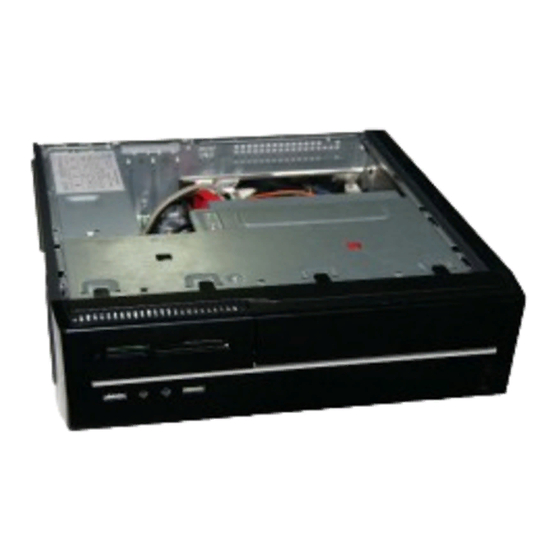
Small Form Factor Barebone
R40-H1
SPECIFICATION
M/B Configuration
Mini ITX MB--H67S
Reset Button
重启按钮
Dimension (W/H/D)
95*282*283(mm)
重啟開關
リセットボタン
1*5.25" External
재설정 버튼
Reset-Taste
Drive Bays
1*3.5" External (Short)
Botón de reinicio
Bouton de remise
1*3.5" Internal
Sıfırlama Düğmesi
Tasto Reset(Ripristino)
2*USB2.0
Botão Reiniciar
Кнопка Reset
Front I/O Ports
1* Micphone,
przycisk resetowania
Alaphelyzet gomb
1* Earphone
SPS
DSI250P
Fan
80*80*20mm
P/N:3A251B800-000-G
*
Bezel View
Optical Disk Drive
Microphone In
光驱
音频输入端口
光碟機
音源輸入
光学ディスクドライブ
マイク入力
옵티컬 디스크 드라이브
마이크 입력
Optisches Laufwerk
Mikrofon-Eingang
Unidad de disco Optico
Entrada de micrófono
l'unité de disques optique
Entrée microphone
Mikrofon Girişi Optik Disk Sürücü
Mikrofon Girişi
unità disco ottico
Ingresso microfono
Drive do disco óptico
Entrada microfone
Оптический привод
Вход микрофона
stacja dysków optycznych
wejście mikrofonu
Optikai lemezmeghajtó
Mikrofon bemenet
USB Port
USB接口
USB
埠
USBポット
USB포트
USB-Anschluss
Puerto de USB
Port USB
USB Bağlantı Noktası
Porta USB
Porta USB
Порт USB
Port USB
USB csatlakozó
Power Button
电源开关
電源開關
パワーボタン
전원 버튼
Power-Taste
Botón de encendido
Bouton de puissance
Güç Düğmesi
Tasto Power
Botão Alimentação
Кнопка питания
przycisk zasilania
Üzemkapcsoló gomb
Line Out
音频输出端口
音源輸出
ラインアウト
라인 출력
Line-Ausgang
linea de Salida
Sortie ligne
HatÇıkışı
Uscita linea
Saída de linha
Линейный выход
wyjście liniowe
Vonalszintű kimenet
1. Wring push pin, remove CPU cooler.
2.Release the CPU socket lever.
2
1
6. When CPU is properly seated, replace the
metal cover and push the CPU socket lever
back to its located position.
5.Check pin marking (triangle) with the pin one of the CPU socket,
3. Lift the metal cover on the CPU socket.
4. Remove the protective socket cover.
align the CPU notches with socket alignment keys and gently put
the CPU onto the socket.
Install CPU Cooler and Heatsink