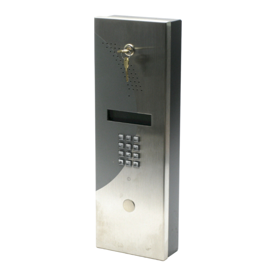
DSC MAXSYS PC4850 Installatiehandleiding - Pagina 6
Blader online of download pdf Installatiehandleiding voor {categorie_naam} DSC MAXSYS PC4850. DSC MAXSYS PC4850 16 pagina's. Telephone entry module

Section 2: Installing & Wiring PC4850
2.1 Unpacking the PC4850
Check that the following parts are in your PC4850 package:
• 1 - PC4850-C cabinet
• 1 - PC4850 board (mounted in cabinet)
• 1 - Speaker (mounted in cabinet)
• 1 - 16V
, 40VA transformer (N.A. only)
AC
• 1 - Postal bracket (mounted in cabinet)
• 1 - Postal lock delete plate (mounted in cabinet)
• 1 - Hole plug (mounted in cabinet door)
2.2 Preparing a Mounting Location (Indoor or
Outdoor Use for UL/ULC only)
1. Select a mounting location for
the PC4850 using the following
guidelines:
• close to the entry door
• away from areas with a large
amount of background noise.
NOTE: It is recommended that you
mount the PC4850 so that the top
of the keypad is no higher than 46
inches (117cm) from the floor.
NOTE: If mounting the PC4850 on
a gatepost, mount it on the post which does not
receive continuous vibration when the gate closes.
2. Schedule Telephone Company Set up
Inform the local telephone company that you will be
installing communication equipment. They may need to
know the FCC registration number of the system. The
FCC number is on a label inside the PC4850 cabinet.
If necessary, schedule an appointment for the telephone
company to install an RJ-11 jack for the building. If you
are installing more than one PC4850 module, only one
module will need an RJ-11 jack.
2.3 Installing a Postal Lock
If you need to install a
postal lock, you should
install it before you
mount the PC4850 cabi-
net. The Postal Switch
Kit (optional) must be
ordered separately. If
you will not be install-
ing a postal lock, you
should leave the postal
lock delete plate and
postal bracket in place.
To install the postal
lock:
1. Undo the nuts hold-
ing the postal lock
delete
plate
place, and remove
the plate. Keep the nuts for step 4.
2. Remove the postal bracket (leave the support cables
attached).
2
46 inches
(117cm)
Floor
Postal
Bracket
Postal Lock
Delete Plate*
Postal Lock
Hole Plug
Postal Lock
Switch
in
*Remove if installing a Postal Lock
3. Use a screwdriver to lift the prongs on the postal lock
hole plug, and remove the plug from the hole.
4. Replace the postal bracket on the posts, and secure it
with the nuts you removed in step 1.
5. Slide the postal lock switch onto posts C and D, and
secure it with the provided nuts.
6. Connect the postal lock switch to the
PO and + BAT terminals as shown.
7. Install the postal lock to posts A and
B on the postal bracket.
2.4 Installing the PC4850
Mount the panel in a dry area close to
an unswitched AC power source. Use
appropriate wall anchors when securing the panel to
drywall, plaster, concrete, brick or similar surfaces.
NOTE: You must complete all wiring before connect-
ing the battery, or applying AC to the panel.
2.5 Connecting Door Strikes
Please see the door strikes manufacturer's instructions
when connecting door strikes.
The PC4850 can support AC and DC door strikes. It is
important to use the properly rated AC transformer, usu-
ally 8 to 24 V
. Please see the door strike Installation
AC
Manual and use the recommended transformer for your
particular door strike.
If an AC door strike is used, please see the diagram in the
'AC Door Strikes' section. The PC4850 provides an AC
output for door 1 at terminals L1/L2 and for door 2 at
terminals NO/NC.
If a DC door strike is used, please see the diagram in the
'DC Door Strikes' section. The PC4850 provides a DC out-
put for door 1 at terminals L3(+)/L4(-). If a DC output is
needed for door 2, an external bridge rectifier is required as
shown in the wiring diagram. When connecting magnetic
locks please see Section 2.6, 'Connecting Magnetic Locks'.
NOTE: For UL applications, if gates are used as part of
the access control system, they must be evaluated to
UL325.
AC (Buzzing) Door Strikes
If you will be connecting AC door strikes, follow the dia-
gram below:
+BAT
Postal Lock
NO Contact
Use AWG#18
Do not connect transformer
to a receptacle controlled
by a switch. For UL Listed
Class2, 16V
, 40VA
AC
PO
