Abstract Data ADE-32 OCTOCONTROLLER Gebruikershandleiding - Pagina 6
Blader online of download pdf Gebruikershandleiding voor {categorie_naam} Abstract Data ADE-32 OCTOCONTROLLER. Abstract Data ADE-32 OCTOCONTROLLER 18 pagina's. Control, modulation, triggering and pattern module with 12 output types individually assignable to 8 simultaneous outputs.
Ook voor Abstract Data ADE-32 OCTOCONTROLLER: Gebruikershandleiding (11 pagina's)

4) Quick Start
1) SET THE TEMPO
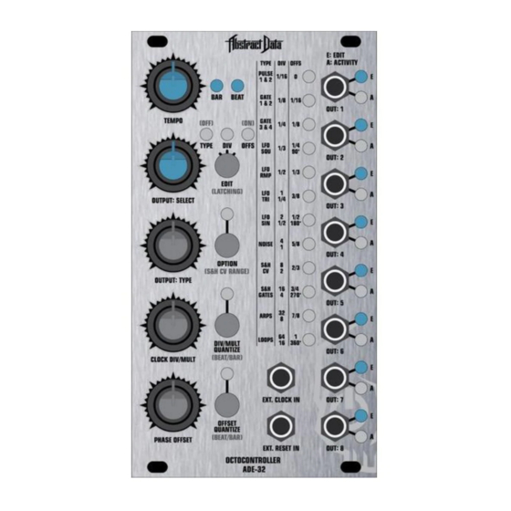
Set the tempo to the desired speed using the TEMPO knob.
The tempo is indicated by the two blue LEDs immediately to the right of the TEMPO knob.
2) SELECT AN OUTPUT TO EDIT
Select an output to edit using the OUTPUT: SELECT knob.
As you move the knob back and forth, the blue LEDs on the right hand side of the front panel
will update to indicate the selected output.
Set the OUTPUT: SELECT knob so that the blue LED at OUT: 1 is illuminated.
3) ASSIGN AN OUTPUT TYPE TO THE SELECTED OUTPUT
Select an output type to assign to the selected output using the OUTPUT: TYPE knob.
As you move the knob back and forth, the vertical row of 12 white LEDs to the left of the outputs
will update and illuminate to indicate the output type that has been selected.
Set the OUTPUT: TYPE knob so that LED 5 is illuminated.
Read across to the left column of text labelled TYPE – this indicates that LFO RMP has been
assigned to the selected output.
4) SET THE CLOCK DIVISION
Set the clock division/multiple for the selected output type at the selected output using the CLOCK
DIV/MULT knob.
As you move the knob back and forth, the vertical row of 12 white LEDs to the left of the outputs
will update and illuminate to indicate the selected clock division/multiple.
Set the CLOCK DIV/MULT knob so that LED 8 is illuminated.
Read across to the middle column of text labelled DIV – this indicates that the output type now has
a length of 4 Beats / 1 Bar at the current tempo.
5) SET THE PHASE OFFSET
Set the phase offset for the selected output type and output using the PHASE OFFSET knob.
As you move the knob back and forth, the vertical row of 12 white LEDs to the left of the outputs
will update and illuminate to indicate the phase offset that has been selected.
Set the PHASE OFFSET knob so that LED 7 is illuminated.
Read across to the right column of text labelled OFFS – this indicates that the output type now has
a phase offset of 180 degrees.
6) REVIEW THE PATCH SETTINGS
Single-click the EDIT button to cycle through the TYPE (output type), DIV (clock division/multiple)
and OFFS (phase offset) settings for the selected output.
The vertical row of 12 white LEDs to the left of the outputs will update to show the current settings
for each of the 3 parameters for the selected output.
7) SYNC TO EXTERNAL CLOCK
Set the PPQ/Clock Resolution of both the ADE-32 and the device you're using as your master clock
to the same PPQ settings. See Page 8 for more details.
Switch the module into External Clock Mode by simultaneously clicking the EDIT and DIV/MULT
buttons. See Page 5 for more details.
© 2016 Abstract Data Ltd.
Page 4 of 15
Version 1.1.3
