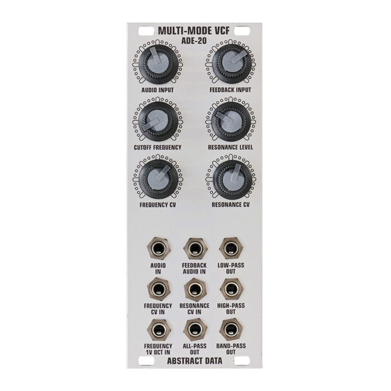
Abstract Data ADE-20 Gebruikershandleiding - Pagina 4
Blader online of download pdf Gebruikershandleiding voor {categorie_naam} Abstract Data ADE-20. Abstract Data ADE-20 4 pagina's. Multi-mode vcf 2 pole, 12db, multi-mode, voltage controlled filter with simultaneous low, high, band and all-pass outputs and complete cv control

3: Technical
HARDWARE:
CALIBRATION:
PRECAUTIONS:
CREDITS:
© 2012 Abstract Data Ltd.
Controls (Left):
Controls (Right):
Inputs (Audio):
Inputs (CV):
Outputs (Signal):
Power Requirements:
Current Draw:
Dimensions:
Supplied Accessories:
Each ADE-20 is calibrated before shipping to provide the best balance
between sound and performance. This includes maximizing the range
of self-oscillation, getting the best sine wave shape and ensuring the
filter responds quickly to changes in Resonance at low frequencies.
Because the ADE-20 uses 'discrete' OTAs (Operational Transconductance
Amplifier) there are some performance characteristics that set it apart from
other filters.
Firstly, the 1V OCT tracking is limited to about 1 octave.
This can be fine-tuned or re-calibrated by the user.
(Please see '1V OCT CALIBRATION' on page 3 of this guide)
Secondly, under certain settings, there may be a small amount of 'bleed'
from the CV Inputs appearing at the Filter Outputs. This is generally only
noticeable when modulating the Cutoff Frequency at audio rates with high
Resonance levels and low Audio Input levels (or no Audio Input). This is
a common trait of discrete OTA designs and most users believe that this
benefits the overall character and sound of the filter.
For more advice on calibrating the ADE-20 please contact Abstract Data.
The ADE-20 uses the Doepfer standard for power connection and cable
orientation. The RED stripe on the supplied power cable connects to the
NEGATIVE (-12V) rail on the ADE-20 with the RED stripe facing DOWN.
This is marked on the back of the ADE-20 PCB as "-12 RED".
(Please see 'POWER CONNECTOR' on page 3 of this guide)
The ADE-20 has diode and polyfuse protection built in but an incorrectly
connected cable may still cause damage to the module or the power supply.
The rear panel of the ADE-20 has exposed parts and connections. Please
ensure when handling the ADE-20 that the unit is held by the sides of the
front panel or the sides of the PCB.
Rory Dow
Ryan Sarver
Tom Wiltshire
http://www.abstractdata.biz
AUDIO INPUT (+/-50% Gain/Attenuation)
CUTOFF FREQUENCY (Manual)
FREQUENCY CV (External)
FEEDBACK INPUT (+/-50% Gain/Attenuation)
RESONANCE LEVEL (Manual)
RESONANCE CV (External)
2x AC, approx. +/-10V max. (3.5mm)
3x AC/DC, approx. +/-10V max. (3.5mm)
(1x scaled to 1V OCT for Frequency Cutoff)
4x AC: Low, High, Band and All-Pass (3.5mm)
+/-12V via 16-pin, Doepfer-style IDC connector
90mA average
10HP (W); panel to IDC connector 35mm (D)
1x 16-pin, Doepfer-style cable, 4x M3 screws
Page 4 of 4
Version 1.1 December 2012
