3onedata TNS5500D Series Snelle installatiehandleiding - Pagina 2
Blader online of download pdf Snelle installatiehandleiding voor {categorie_naam} 3onedata TNS5500D Series. 3onedata TNS5500D Series 3 pagina's. 12-port series layer 2 wall mounting industrial ethernet switch
Ook voor 3onedata TNS5500D Series: Snelle installatiehandleiding (4 pagina's), Snelle installatiehandleiding (4 pagina's), Snelstarthandleiding (5 pagina's)
dimension to mark two screw positions.
Hang the device on the labeled wall; align the bolt
to the labeled position, then screw the bolt to
enhance stability, installation ends.
【Wall-mounted Device Disassembling】
Power off the device.
Hold the device steady and unscrew the screw on
the wall.
Lift the device upward slightly; take out the device,
disassembling ends.
【DIN-Rail Mounting】
The product adopts 35mm standard DIN-Rail mounting which
is suitable for most industrial scenes, mounting steps are as
follows:
Check if the DIN-Rail spring bracket of the device is
installed firmly.
Clip the upper part of the DIN-Rail mounting kit, i.e.
the fixed side, into the DIN rail.
Press the lower side of the device and insert the
lower part of DIN-Rail mounting kit (the side with
spring support) into DIN-Rail.
Tips:
The DIN-Rail spring support is a metal sheet that can
move up and down, and there will be a sound after it is
clamped in.
Check and confirm the product is firmly installed on
DIN rail, then mounting ends.
【Disassembling DIN-Rail】
Power off the device.
Use a slot type screwdriver or other tools to move
the DIN rail spring support downward; At the same
time, move the lower side of the device outward
and move out the lower part of the DIN rail
mounting kit.
Lift the device upward slightly, move out the upper
part of DIN-Rail mounting kit. Disassembling ends.
Notice Before Powering on:
Power ON operation: First insert the power supply
terminal block into the device power supply interface,
and then plug the power supply plug and power on.
Power OFF operation: First, remove the power plug,
then remove the wiring section of terminal block. Please
pay attention to the above operation sequence.
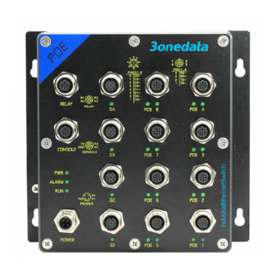
【Power Supply Connection】
This series device provides 1 DC power
input, and the interface adopts M12 A-Coded
4-Pin connector (male), in which the power
supply occupies two pins V- and V+, which
can be connected with M12 A-Coded 4-Pin slot (female).
Model I power input range: 110VDC(66~154VDC);
Model II power input range: 24VDC (9~36VDC).
The pin definitions of M12 (male) are shown as follows:
Definition
V+
V-
Positive
Negative
Description
power
power
input
input
【Relay Connection】
This series of device provides 1 M12
A-Coded
4-Pin
connector
supports 1 relay alarm output. RELAY1 and
RELAY2 are a set of normally open contacts of the device
alarm relay. They are open circuit in the state of normal non
alarm, closed when any alarm information occurs. For
example, they are closed when powered off, and send out
alarm. The relay supports the output of network abnormality
alarm. It can be connected to alarm light, alarm buzzer, or
other switching value collecting devices, which can timely
inform operators when the alarm occurs.
【Service Port Connection】
This series of device provides a program
debugging port of M12 D-Coded 4-Pin (Female)
connector, which can be connected with PC for
CLI command management of the device. The interface
adopts M12 D-Coded 4-Pin slot (male). The pin definitions of
M12 are shown as follows:
Definition
TX
RX
RS-232
RS-232
Description
send
receive
signal
signal
【Communication Interface Connection】
This series of device provides 8 10/100Base-T(X)
interfaces, the interface type is M12 D-Coded 4-Pin
slot (female). The definitions of M12 pin are as
follows:
Pin No.
Pin Definition
Pin Description
RELAY1
RELAY2
Relay
output
terminal blocks
(male)
that
NC
GND
Reserved
Ground