Dametric CMD-DM2 Handmatig - Pagina 3
Blader online of download pdf Handmatig voor {categorie_naam} Dametric CMD-DM2. Dametric CMD-DM2 5 pagina's.

Dametric AB
4.3
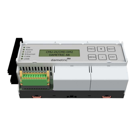
Led indicators
Two of the six led in the front of the unit are used to indicate:
ON
Alarm
Limit
Ethernet
CAN
USB
4.4
CMD Control Motor Driver
Supply voltage
Power consumption
Step motor
Motor output
Phase current, RMS
Phase current, peak
4.4.1
DO - Digital Output
Output voltage
Type
Number
Max current/output
4.4.2
DI - Digital Inputs
Input voltage
Type
Number
Max current/input
5
Handling
5.1
Panel indicators
The led indicators have the following meaning:
Name
Function
ON
Power supply
Alarm
Alarm indication
Limit
Not used
Ethernet
Not used
CAN
Not used
USB
Not used
5.2
Configuration
A few parameters are used to give the user the desired operation.
A parameter list is used to document the settings of the unit. Be sure to keep this up to date in case the module
must be replaced.
5.2.1
Configuration of the parameters with the built-in display and buttons
To select the function – press MENU first and scroll with PREV and NEXT until the chosen function is
shown. The basic information of the function is displayed, and this can be a parameter value or a measured
value.
Press PLUS to select one of the parameters associated with the selected function. Use PLUS and MINUS to
scroll among the parameters.
Use MENU if you select to go back to the function level.
Press MENU for more than 1 second to return to the basic display indication.
CMD-DM2 Manual EN.docx
CMD-DM2
Green, indicates power supply
Red, on if there is any alarm in the unit
Not used
Not used
Not used
Not used.
24 VDC, ± 10 %
Nominal 0.4 A, max. 2A, depending of CMD activation
CM-2NMHK with cable K-CM25K
2-phase, A+, A-, B+, B-
max 1.5A
Max 2.3A
24VDC
PNP type
1 digital outputs
200mA
24VDC
Active high
3 digital inputs
5mA
off
No power supply
No alarm activated
-
-
-
-
flashes
-
An alarm detected
-
-
-
-
Nov. 21, 2019
Manual
on
Power supply OK
A sum alarm detected
-
-
-
-
Page 3 of 5
