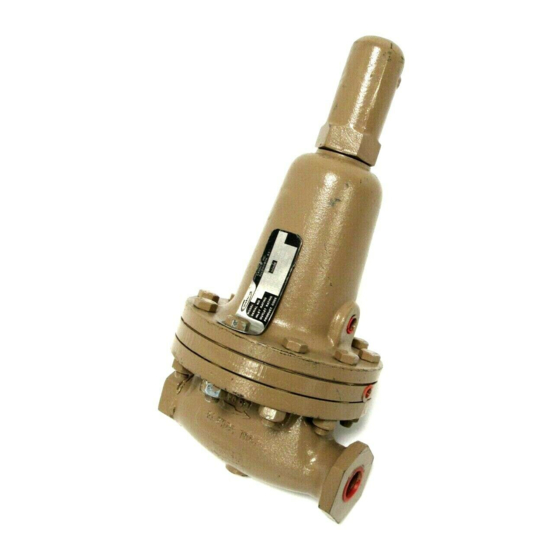
cashco 1000HP-1PLUS8 Installatie-, bedienings- en onderhoudshandleiding - Pagina 5
Blader online of download pdf Installatie-, bedienings- en onderhoudshandleiding voor {categorie_naam} cashco 1000HP-1PLUS8. cashco 1000HP-1PLUS8 17 pagina's. Differential pressure reducing regulator

9. Place the pusher plate stud (13) in a separate
vise, gripping the stud (13) on the hexagonal
cast-in-place edges located on the un der neath
side of the pusher plate stud. NOTE: Do not
remove the stud nut (10), stud collar (16), and
the location locking cotter pin (15).
10. Loosen and remove nut (11).
11. Lift and remove pressure plate (3) and O-ring
(50).
12. Remove upper diaphragm(s) (20), diaphragm
spacer (41) and body spacer (42).
13. Pry loose pusher plate and stud (13) from lower
diaphragm(s) (20) or from lower pusher plate
gasket (12). (Pusher plate gasket (12) is not
utilized with composition (soft) di a phragm.)
Remove the diaphragm(s) (20).
14. Remove pusher plate gasket (12) from push er
plate and stud (13).
15. Clean gasket sealing surfaces of pusher plate
and stud (13), spring chamber (2), body (1),
and pres sure plate (3) thoroughly.
16. Install new pusher plate gasket (12) over
pusher plate and stud (13).
17. Install one-half of total quantity of new
diaphragm(s) (20) over pusher plate and stud
(13). NOTE: Refer to quantity of diaphragms
(20) incorporated in the bill of materials
listing. Depending on outlet pressure level,
var i ous quantities of metal diaphragms will be
"stacked". They should always be in multiples
of two for -1+8 option.
18. Place diaphragm spacer (41) over pusher
plate and stud. Place body spacer (42) over
outer perimeter of diaphragm(s) (20).
19. Install remaining quan ti ty of diaphragm(s) (20)
over pusher plate and stud (13).
20. Place O-ring (50) over push er plate and stud
(13).
21. Inspect pressure plate (3) to ensure no
de for ma tion due to over-pressurization.
If de formed, bent, or otherwise distorted,
replace.
22. Ensuring that the curved outer rim side of the
pressure plate (3) is down, place the pressure
5
plate (3) over the pusher plate and stud (13).
Place nut (11) onto the stud (13) and tighten.
Recommended torques are as follows:
Body Size
Metal Diaphragm Comp. Diaphragm
3/8" – 1/2"
45–50 ft. lbs.
3/4" – 1"
45–50 ft. lbs.
1-1/4" – 2"
80–90 ft. lbs.
Use two flange bolts (8) to keep mul ti ple
di a phragms' (20) bolt holes prop er ly aligned
while tight en ing the nut (11).
CAUTION
Do not use your fingers to hold diaphragms (20)
during tightening of nut (11)!
23. Remove cotter pin (15) securing stud nut (10)
to lower end of pusher plate and stud (13),
and replace with a new pin (15). (Do not allow
the stud nut (10) to move when the cotter pin
(15) is removed.)
24. Remove rocker arm shaft (17) and rock er
arm (14). Measure inside of rocker arm (14)
"prongs" as in di cat ed in the following di a gram.
If either of the below di men sions are exceeded
by 1/8" (3mm), re place rocker arm (14).
Valve Size
DIM
MAT'L
1/2"
(DN15)
A
BRZ
7/8"
22 mm
B
BRZ
5/8"
16 mm
A
SST
13/16"
21 mm
B
SST
9/16"
14 mm
DIM
MAT'L
1-1/4"
(DN32)
A
BRZ
1-13/16"
46 mm
B
BRZ
29/32"
23 mm
A
SST
1-1/2"
38 mm
B
SST
11/16"
17 mm
25–30 ft. lbs.
30–45 ft. lbs.
50–60 ft. lbs.
3/4"
(DN20)
1"
(DN25)
1-5/32"
29 mm
1-7/16"
37 mm
25/32"
20 mm
3/4"
20 mm
1-1/16"
27 mm
1-7/16"
37 mm
23/32"
18 mm
3/4"
20 mm
1-1/2"
(DN40)
2"
(DN 50)
1-25/32"
45 mm
2-3/16"
56 mm
7/8"
22 mm
29/32"
23 mm
1-25/32"
45 mm
2-5/32'
55 mm
7/8"
22 mm
29/32"
23 mm
IOM-1000HP-Dif fer en tial
