cashco 6A00 Instructies voor installatie, bediening en onderhoud - Pagina 4
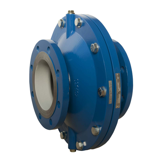
Blader online of download pdf Instructies voor installatie, bediening en onderhoud voor {categorie_naam} cashco 6A00. cashco 6A00 7 pagina's. Inline deflagration flame arrestor
Ook voor cashco 6A00: Installatie-, Bedienings- en Onderhoudshandleiding (8 pagina's)
Chapter III
III. TRANSPORT AND STORAGE
The flame arrestor shall be packed carefully in order to prevent damages or impurity during the transport
or storage.
Chapter IV
IV. INSTALLATION AND ASSEMBLY
Basically, the installation and assembly of the flame arrestor is carried out considering the respective
application limits and regulations for the scope, especially the appropriate instruction for accident
prevention by the customer.
The installation starts with removing the plug connection/flange cover at the inlet and outlet of the flame
arrestor. The threads respectively the facing of the flanges shall be checked on damages, foreign material
or dirt. The assembly is possible horizontally as well as vertically. A tensionless fitting shall be guaranteed.
Additionally, attention shall be paid to the fact that the flame arrestor is not used as a bearing position. If
the flame arrestor is marked with a sticker "Protected side" this side has to be installed opposing the
potential ignition source. With bi‐directionally working flame arrestors a positioning considering the
potential ignition source is not required.
For inline flame arrestors the pipe size on the protected side shall not be smaller than the one on the
unprotected side. For inline flame arrestors the pipe size on the unprotected side shall not be bigger than
the connection size of the flame arrestor. The distance (L
) between the potential ignition source and the
u
deflagration inline flame arrestor shall not exceed the data given in the charts 1‐3.
If the flame arrestor is marked as "Protected against endurance burning" (BC: a), it must not be insulated or
encased. With a marking "Protected against short burning" (BC: b) at least one screw plug including the
used seal ring has to be removed after assembling the flame arrestor. It shall be replaced by the included
resistance thermometer (PT100) + seal ring. If a stabilized burning is possible on both sides, at least one
temperature sensing device shall be installed on each side. The installation guidelines by the manufacturer
of the resistance thermometer and his requirements of compliance shall be fulfilled. Then the installed
temperature sensing device or devices will have to be integrated into the complete system in order to
activate an emergency function. The circuit must permit a clearing of the ominous state within 50% of the
burn time stated on the warning sign. Resistance thermometers of other brands may be used if their
measure features are identical with the measure features of the resistance thermometers used in testing,
and if the electrical explosion protection meets the respective application conditions of the flame arrestor.
In order to guarantee that no gap to the atmosphere has developed a leakage test should be carried out
before initial operation. Attention! Exceeding the test pressures stated in the inspection certificate
(EN10204) is ineligible.
04/16
Page 4