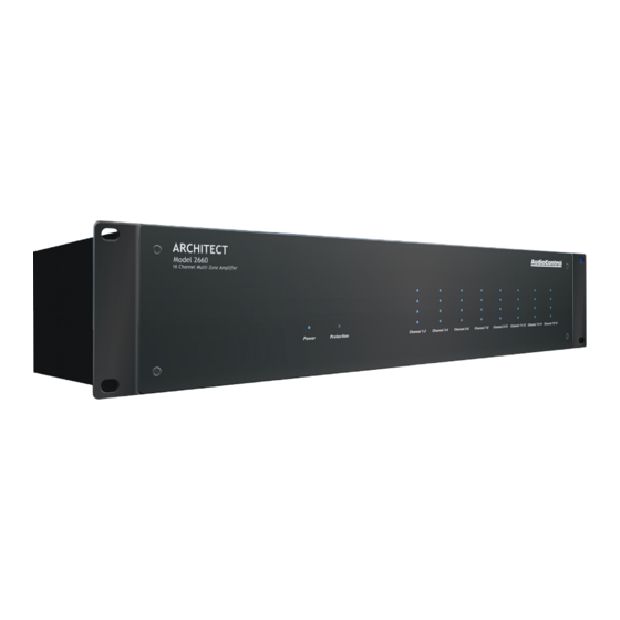
AudioControl ARCHITECT P2660 Installatiehandleiding - Pagina 9
Blader online of download pdf Installatiehandleiding voor {categorie_naam} AudioControl ARCHITECT P2660. AudioControl ARCHITECT P2660 15 pagina's. 16 channel multi-zone power amplifier

Almost Done With The Rear Panel
2
3
5
1
4
11. 12V Local Trigger – This TS 1/8" con-
nector allows each zone to be individu-
ally turned on or put into standby.
The local 12V trigger takes priority
over the signal sense circuit. Whenever
a plug is inserted into the 12V trigger
input jack, signal sense is disabled in
that zone.
Note: The local 12V trigger can-
not activate a zone unless the
master trigger is also activated
or jumpered on.
Pinout:
Tip
= Input
Sleev
e = Ground
Using a contact closure:
An open connection will set the zone
to active.
Shorting the tip to the sleeve will set
the zone to standby.
Using a 12V trigger source:
Connect the source ground to the
sleeve.
Connect the source output to the tip.
A voltage of +3V to +12V will set the
zone to active; 0V will set the zone to
standby.
16
7
8
9 10
11
6
13
12
Zone Active LED – This LED will turn
blue whenever the zone is active. The
LED will be off whenever the zone is in
standby.
12. Local Inputs – These are line-level
analog RCA stereo inputs. These local
inputs may be selected to play in this
zone by setting DIP switch 3 to the left.
Local Inputs may not be bussed to
other zones. For Matrix bussing capa-
bility (and a plethora of other really
cool features) please see our Director
Matrix M6400.
13. Speaker Outputs – This 4-pin con-
nector allows easy connection of two
speakers for stereo operation, or one
speaker for bridged mono operation.
Stereo Speaker Connection:
Set the zone's Dip switch 1 to the left
(stereo). Note the polarity markings.
The speaker impedance should
be 4 Ohms minimum in stereo
operation.
1
Bridged Mono Speaker Connection:
Set the zone's Dip switch 1 to the right
(mono). Note the polarity markings. In
this mode, the input signals are com-
bined in mono, and the power from
both channels is combined to drive a
single speaker.
The speaker impedance should
be 8 Ohms minimum in bridged
mono operation.
1
To run two speakers in dual-mono,
connect them in the same way as
shown in the stereo speaker diagram
above.
Almost Done With The Rear Panel
Speaker Connections
Establish a standard connection color
code and stick with it. One conductor of
the speaker wire is normally marked by
a different color (silver versus copper) or
there is a ribbing on one side. Typically this
marked conductor is used for the positive
(+) speaker leads. Really good wire has
Positive and Negative printed right onto
the wire jacket.
Match the polarity markings on the
unit with the polarity markings on your
speakers.
See the next page for some handy
information about speaker and wiring
impedance.
ARCHITECT
™
Model 2660
Installation Manual
17
