Dantel 46019 Installatie- en bedieningshandleiding - Pagina 3
Blader online of download pdf Installatie- en bedieningshandleiding voor {categorie_naam} Dantel 46019. Dantel 46019 10 pagina's. Summary alarm module

CIRCUIT DESCRIPTION
46019-0298 <90-00028>
A strap position configures each Latch/Gate circuit to:
♦
Latch: Hold alarm status until released by an external
source.
♦
Follow: Release alarm status when the alarm input returns
to normal.
Reset Inputs and Acknowledge
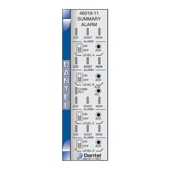
Each alarm input has an individual reset input and acknowledge
button. Initiate reset by applying a standard TTL signal at the
appropriate edge connector pin.
Each Latch/Gate circuit also has a front panel button (ACK)
which acknowledges alarm status and resets the relay. You can
acknowledge by pressing the front panel "ACK ALL" button, the
master reset or the acknowledge timer.
Disable the audible alarm by setting the front panel cutoff
switch to ON.
Output Relays
An individual form-C relay for each alarm level and a common
relay shared by all levels provide external alarm indications.
Each level latch and gate circuit energizes that individual level
relay's operating coil. Each relay has two sets of relay contacts
(visual and audible). Each set has normally open (NO) and
normally closed (NC) contacts.
The common relay operates on any alarm level and remains ON
until all alarms (whether they follow or latch) clear or are
acknowledged.
TTL/OC Master Reset
A master reset with TTL and OC inputs resets all levels (A, B, C
and D) at the same time. Reset levels by applying a single signal
to the appropriate edge connector pin.
Acknowledge Timer
An acknowledge timer automatically acknowledges alarms after
the preset time interval expires. You can set the unit for a 0, 0.5,
1.0, 4.0 or 8.0 minute delay. If the timer is partially through a
timing cycle when an additinoal alarm status change occurs, the
timer begins again with the new alarm.
Regulated Power Supply
The regulated power supply operates on -21 to -56 VDC input
power and provides ±12 VDC and +5 VDC output power for the
SAM circuits. The ±12 VDC and +5 VDC ouptput power routes
to edge connector pins for off-board use.
P
3
AGE
