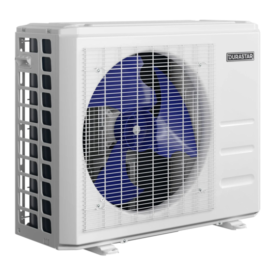
DURASTAR DRA4U36M1A Installatiehandleiding - Pagina 5
Blader online of download pdf Installatiehandleiding voor {categorie_naam} DURASTAR DRA4U36M1A. DURASTAR DRA4U36M1A 7 pagina's. Third-party thermostat interface
Ook voor DURASTAR DRA4U36M1A: Gebruikershandleiding (16 pagina's)

WARNING
• All wires must meet National Electric Code ( NEC ) as well as local codes for proper sizes. Use the Electrical Data
Table minimum circuit amps ( MCA ) and maximum over current protection ( MOCP ) to determine the proper wire
sizes and fuse or breakers for the installation.
NOTE
• Only use 14/4 AWG stranded and shielded wire.
• Thermostat G to interface G is default.
• Verify power supply.
• The remote control can only be used to set the Swing and LED functions on appropriate indoor models after the
thermostat interface is installed.
Configuring the DIP Switches
Follow the instructions below to configure the DIP switches on the interface's board.
For Durastar systems, both DIP switches 1-1 and 1-2 need to be set in the ON position.
The DIP switch sets are numbered from right to left.
DIP Switch 1-1
This switch turns on the Control Box display.
SW 1-1
Result
Remarks
ON
Display On
Required
OFF
Display Off
Default
DIP Switch 1-2
Used to determine unit type.
SW 1-2
Result
Remarks
Ductless indoor
ON
Required
and outdoor unit.
Ductless outdoor
OFF
Default
unit only.
DIP Switch 2-1
This switch selects the system operation. Leave on default.
SW 2-1
Result
Remarks
ON
Cooling Only
OFF
Heat Pump
Default
DURASTAR.COM
DIP Switch 2-2
This switch is used for protection of the indoor coil.
Leave on default.
SW 2-2
Result
Remarks
ON
Fans do not stop
Fans stop if indoor
OFF
coil temperature
Default
is low
DIP Switch 3-1
This switch is used to activate the Dry function.
Leave on default.
SW 3-1
Result
Remarks
ON
Dry On
OFF
Dry Off
Default
DIP Switch 3-2
This switch forces the Compressor to run longer if
temperature not reached after one (1) hour.
Leave on default.
SW 3-2
Result
Remarks
ON
+1hr
OFF
+30 minutes
Default
DIP Switch 4-1 & DIP Switch 4-2
These switches are for factory testing purposes only.
Leave on default/(OFF).
8
Error Codes
Error Code
Remarks
E0
Indoor EEPROM error
E2
Cross-Zero detection error
E3
Indoor fan speed malfunction
E4
Indoor room temperature sensor error
E5
Evaporator temperature sensor error
EC
Refrigerant leak detected
F0
Current overload protection
F1
Outdoor ambient temperature sensor (T4) malfunction
F2
Condenser temperature sensor (T3) malfunction
F3
Condenser temperature sensor (T5) malfunction
F4
Outdoor unit EEPROM parameter error
F5
Outdoor fan speed has been out of control
F6
T2b sensor error
P0
Inverter module (IPM) malfunction
P1
Over-voltage or under-voltage protection
P2
Compressor high temperature protection (OLP)
P3
Low ambient temperature cut off in heating
P4
Compressor drive malfunction
P6
Compressor low-pressure protection
00
Module boot mode and indoor running mode for power off
IN
Module and indoor unit communication malfunction
OU
Module and outdoor unit communication malfunction
9
DURASTAR.COM
