Apollo Valves DC4A Installatie-, bedienings- en onderhoudshandleiding - Pagina 6
Blader online of download pdf Installatie-, bedienings- en onderhoudshandleiding voor {categorie_naam} Apollo Valves DC4A. Apollo Valves DC4A 12 pagina's. 1/2 inch - 2 inch double check valve (dc) backflow preventer

INSTALLATION, OPERATION, & MAINTENANCE MANUAL
V. TESTING PROCEDURES
This test is performed with the Differential Pressure Gauge Test Kit . The Differential Pressure Gauge simply measures the pressure
drop across the check valve . This pressure drop is normally the same as the strength of the check valve spring . In using the
Differential Pressure Gauge to test the Double Check assembly, a minimum of 1 .0 psid is required for each check valve in order
for that check valve to pass the test . Such a small reading is often difficult to read on most test kits . This is one of the drawbacks
of this test . However, since the first shut-off valve is left in the open position for this test, it is possible to use this test when the
first shut-off valve is leaking badly .
NOTE: This is a three-valve test kit procedure and may or may not be approved in all jurisdictions. Consult your local water
purveyor for acceptable test procedures.
Test Setup
1 .
Notify customer that the water service will be off . Identify the make, model, and serial number on the backflow device .
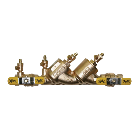
Inspect that this is an approved assembly - two check valves, two shut-off valves and four test cocks . Observe the area to
make sure there are no leaks .
2 .
Flush test cocks (1, 2, 3 & 4), then close all test cocks .
3 .
Install appropriate adapters (if necessary) .
4 .
Close shut-off valve #2 .
TEST NO. 1
PURPOSE: To test check valve #1
1 .
Close all valves on test kit .
2 .
Connect the high side hose to test cock #2 and the low side hose to test cock #3 . Open test cock #2 and test cock #3 .
3 .
Open vent valve "C" and high "A" on the test kit to bleed air from the high side of the kit . Close high "A" valve and then
open low "B" valve to bleed the low side . Close low "B" valve .
4 .
Record the gauge reading . It must be a minimum of 1 .0 psid in order to pass . Close test cock #2 and test cock #3 .
TEST NO. 2
PURPOSE: To test check valve #2
1 .
Move the high side hose to test cock #3 and the low side hose to test cock #4 . Open test cock #3 and test cock #4 .
2 .
Open vent "C" valve . Then open high "A" and bleed air from the high side of the kit . Close high "A" valve, and then open low
"B" valve and bleed the low side of the kit . Close low "B" valve .
3 .
Record the gauge reading . It must be a minimum of 1 .0 psid in order to pass . Close test cock #3 and test cock #4 . Remove
hoses and test kit . Slowly open shut-off valve #2 in order to restore water flow to the facility, placing the DC back into service .
6
Customer Service (704) 841-6000
www.apollovalves.com
