Cavotec MC-3-5 Bedienings- en onderhoudshandleiding - Pagina 5
Blader online of download pdf Bedienings- en onderhoudshandleiding voor {categorie_naam} Cavotec MC-3-5. Cavotec MC-3-5 9 pagina's. Industrial remote control
Micro-control as
1.3 Environment
Terminal and Base Unit are designed for use with ambient temperatures between -25°C and +50°C.
The housings are also tested against dust and water ingress to IP-65 (optionally the terminal can
have an IP-66 classification).
The battery charger is IP40, install in a clean and dry area, temperature between +10°C and +40°C.
1.4 Documentation
The documentation with an MC-3-series system consists of the following documents:-
•
This Operation and Maintenance Manual
•
Wiring diagrams
•
Layout drawings
•
Bill of materials, connections and configuration sheets
•
Additional Manuals specific to the delivery (optional)
•
Additional Module specifications if required (optional)
2. Operating and Maintenance
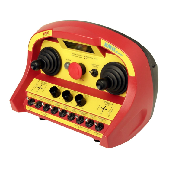
2.1 Terminal
All the MC-3-series terminals are produced in accordance with the customer's specifications and the
operation will vary between deliveries. It is important that the operator is familiar with the machine
being controlled and has been given the necessary training.
This document deals with MC-3-series generally, and special instructions in the use of the terminal
cannot be given here. The functions that are described in this chapter are common for all MC-3-series
deliveries. Micro-control can supply manuals for specific machines if requested to do so.
2.1.1 Operating the terminal
Check that a fully charged battery is in the terminal. Pull/twist the Emergency Stop pushbutton out
and turn the terminal ON. Press the start pushbutton if fitted. After a self test (approx 1 second) the
terminal will establish contact with the base unit.
2.1.2 Maintenance
If the terminal is dirty it must be cleaned with a damp cloth to ensure that:-
• Symbols and text can be read.
• Aggressive chemicals cannot corrode the rubber boots of joysticks and switches.
If the rubber boots of the joysticks are damaged, replace them at once.
• Prevent deposit of salt or dirt on buttons or handles which in turn may involve malfunction.
The terminal contains advanced electronic equipment and should be treated accordingly.
2.1.3 Display Codes
A yellow light emitting diode is used to indicate the status of the system. The most common
indications are:-
•
Steady light - normal operation, no errors are detected and the battery voltage is OK.
•
Flashing light (1 flash per second)- battery voltage is low. Change the battery.
•
2 short flashes per second – One or more of the joysticks or switches are active when the
terminal is turned on. Deactivate the functions and the terminal will start normally.
Further indications are listed in the enclosed table.
MAN-05-006
Operation and Maintenance Manual for MC-3-series
Page 5 of 9
Rev. 1