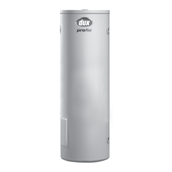
Dux ProFlo 400T236 Gebruikershandleiding - Pagina 8
Blader online of download pdf Gebruikershandleiding voor {categorie_naam} Dux ProFlo 400T236. Dux ProFlo 400T236 16 pagina's. Electric storage water heaters
Ook voor Dux ProFlo 400T236: Gebruikershandleiding (16 pagina's), Gebruikershandleiding (16 pagina's)

Owner's Manual – Proflo Electric Storage Water Heaters
Electrical Connection
General:
This water heater is designed for single
phase 240V a.c. supply only. The
electrical connection must comply with
Local Supply Authority Regulations and
AS/NZS 3000.
Connection of the electrical wiring
must only be carried out by a licensed
tradesperson.
Connections are made at the terminal
block under the water heater electrical
cover. A means for disconnection must
be incorporated in the fixed wiring in
accordance with the Wiring Rules.
Removing the Electrical Cover:
Before removing the electrical cover,
ensure the electrical power supply is
safely isolated.
The electrical cover is removed by
undoing the two screws at the bottom
of the cover and sliding the cover
downwards to disengage the top edge.
Connections:
The cable entry is a pre-punched hole
designed to accept a 20 mm conduit
gland. It is located adjacent to the
terminal block.
To prevent damage to the wiring, the
cable entry must be fitted with a gland
prior to feeding the wiring through the
hole. Ensure the conduit entry is sealed
correctly.
6
Connect the active and neutral wires to
the terminal block and the earth wire to
the earth tab (located on the right hand
side). Excess wire is not to be looped
close to the thermostat or tank.
Replacing the Electrical Cover:
1. Press the reset button on the
thermostat to ensure the over-
temperature energy cut-out is set.
2. Check the Pressure & Temperature
Relief Valve, both of the brass plugs,
and their clear plastic packaging
have been removed from inside the
cover.
3. Ensure the terminal block mounting
plate is horizontal.
4. Slide the cover up, ensuring the top
edge engages under the case.
5. Swing the cover down until the
bottom edge contacts the case.
Ensure the terminal block mounting
plate is below the pins located
inside the cover.
6. Refit and tighten both screws in the
cover.
Ensure the water heater is filled
with water before turning on the
electricity supply.
H0421
0421
Rev. N
