4ms EnvVCA Gebruikershandleiding - Pagina 10
Blader online of download pdf Gebruikershandleiding voor {categorie_naam} 4ms EnvVCA. 4ms EnvVCA 12 pagina's.
Ook voor 4ms EnvVCA: Gebruikershandleiding (20 pagina's)

portion of the envelope. On the other hand, if we had only patched
into the Follow jack, then a short gate width would only produce a
complete envelope if the rise time parameter was very fast. Gates
that are shorter than the rise time will result in an envelope that
doesn't reach the peak, as seen in Figure 6 of the previous section.
By patching the gate into both the Trigger and Follow jacks, we get
complete envelopes regardless of the settings, as seen in Figure 7.
Notice the width of the pulses and how they correlate to the sustain
of the envelope output. The first pulse is not wide enough to produce
any sustain because its width is lesser than the time it takes for the
envelope to rise.
Cycle off
Atten. sets
sustain level
Atten.
Rise adjusts
attack
Fall adjusts
decay, release
time
Fall CV
adjusts decay
time
Gate from
CV/Gate
keyboard or
In
sequencer
(width sets
sustain time)
Out
From sound
source
To mixer/
output amp
Figure 8: ADSR. Attenuator knob turned down in
2nd envelope to lower sustain level. Fall CV turned
up in 3rd envelope to make decay slower.
Slow
Med
Fast
Cycle
Slow
Fast
Rise
Fall
Env. Level
Rise CV
Fall CV
Time CV
Env
Trigger
Cycle
EOR
Follow
Audio
In
Out
EnvVCA
ADSR Envelope
An ADSR (attack-decay-sustain-release) envelope is
like an ASR envelope, except that it adds a fourth stage
known as "decay" after the attack stage. After hitting
the peak, an ADSR envelope "decays" to a sustain
level less than the peak level. See Figure 8.This
sustain level and the speed at which the envelope
decays are controllable. The other stages (sustain and
release) are identical to those in an ASR envelope.
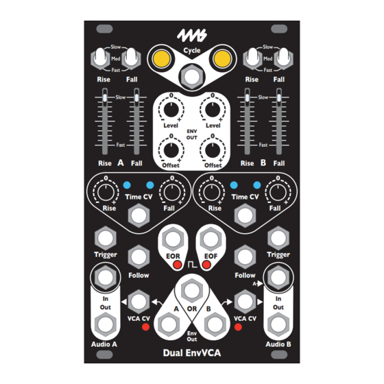
We can generate an ADSR envelope with control over
each stage by extending our ASR patch. This patch
requires a way to attenuate the gate signal. A fictional
attenuator module is shown on the left.
Start with the ASR patch from the previous section.
Unpatch the cable from the keyboard/sequencer gate
output going to the Follow input, and instead patch it
from the keyboard/sequencer gate output to the input
of the attenuator module. Patch the output of the
attenuator to the Follow jack.
Firing a gate will generate an envelope as shown in
Figure 8. The rising edge of the gate will cause the
envelope to rise to its peak and then fall until it reaches
the level set by the Follow jack, which is controlled by
the attenuator knob. For example, setting the
attenuator knob such that the attenuator outputs a 3V
gate will make the envelope sustain at 3V internally
(resulting in a 6V sustain on the Env jack if the Env
Level slider is all the way up). After the gate on the
Follow jack goes low, the envelope will fall back to
zero during the "release" stage.
We now have control over the attack or rise speed
(Rise slider/switch), sustain length (gate pulse width),
and sustain level (gate attenuator). However the decay
time and the release time will always be the same, set
by the Fall slider/switch.
To make this a true ADSR envelope, patch a cable from
the mult or stacking cables on the gate output of the
keyboard or sequencer to the Time CV jack. Make sure
the keyboard/sequencer gate output still goes to the
Trigger jack and attenuator module input. Now you can
use the Fall CV knob to set the decay time relative to
the release time. Turning it to the left of center will
make the decay time faster than the release time, and
vice-versa. The reason this works is that the decay
stage occurs while the gate is high, and the release
Page
10
of
12
Figure 7: ASR patch: Gate length
controls sustain length
