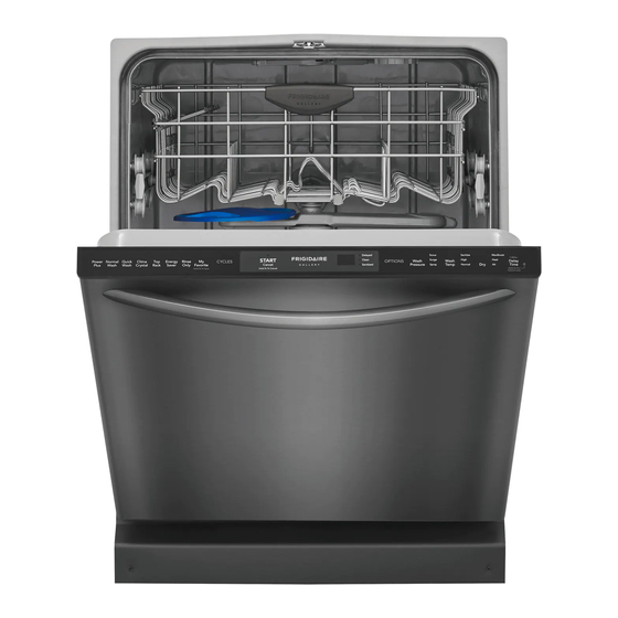
Frigidaire Designer Series Gebruiks- en onderhoudshandleiding - Pagina 5
Blader online of download pdf Gebruiks- en onderhoudshandleiding voor {categorie_naam} Frigidaire Designer Series. Frigidaire Designer Series 20 pagina's. Electronic control a/c
Ook voor Frigidaire Designer Series: Gebruiks- en onderhoudshandleiding (11 pagina's), Productgegevens (1 pagina's), Gebruikershandleiding (14 pagina's), Gebruiks- en onderhoudshandleiding (20 pagina's), Gebruiks- en onderhoudshandleiding (20 pagina's), Handleiding voor installatie-instructies (8 pagina's), Gebruiks- en onderhoudshandleiding (13 pagina's), Gebruiks- en onderhoudshandleiding (11 pagina's), Gebruiks- en onderhoudshandleiding (20 pagina's), Gebruikershandleiding (12 pagina's), Gebruikershandleiding (20 pagina's), Gebruikershandleiding (14 pagina's), Gebruiks- en onderhoudshandleiding (11 pagina's), Gebruiks- en onderhoudshandleiding (11 pagina's), Gebruiks- en onderhoudshandleiding (11 pagina's), Gebruiks- en onderhoudshandleiding (20 pagina's)

