AUSTRALIAN MONITOR MX61 Installatie- en bedieningshandleiding - Pagina 4
Blader online of download pdf Installatie- en bedieningshandleiding voor {categorie_naam} AUSTRALIAN MONITOR MX61. AUSTRALIAN MONITOR MX61 12 pagina's. 6 channel mic/line mixer
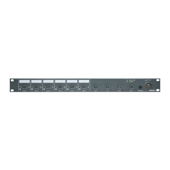
FRONT PANEL
1
2
1
GAIN TRIM
This control is used to adjust the input
gain and affects both the XLR and the
RCA inputs.. The input gain can be
adjusted by +/- 15dB. This allows a wide
rage of program sources to be set up with
optimum gain structure. With the gain trim
in the centre position, the boost/cut is set
to 0dB. See the block diagram on page
10 for details of the gain structure.
2
LEVEL
Controls the level of the input signal.
3
INPUT STATUS LEDS
Each input has an LED status indicator.
The LED is green when there is signal
present and red if the signal is
approaching clip. If the LED begins to light
red this would indicate the internal signal
level is 6dB before clip. Note that the front
panel level control is post status LED and
as such, the status LED is NOT affected
by the level control. If an input channel
is clipping use the gain control to adjust
the correct amount of input level.
4
OUTPUT TONE CONTROLS
The output has a 3 band EQ.
Bass – +/-12dB 100Hz shelving
Mid – +/-12dB 1.6kHz, Q=1.4
Treble – +/-12dB 10kHz shelving
PAGE 4
3
5
MASTER
This pot controls the overall mixed output.
6
HEADPHONE
1
⁄
This
" jack socket allows headphones
4
to be used for monitoring. It can be set
as pre or post master volume control.
See "Internal Adjustments" on page 6.
Default factory setting is pre master
volume control.
7
MASTER VU DISPLAY
This VU display indicates output level.
8
POWER SWITCH
This switch switches power from
the mains. The up position is on.
NOTE: When using the 24VDC
socket the unit is on regardless
of switch position.
9
POWER ON LED
This indicates there is power to the unit.
NOTE: When using the 24VDC
socket the power LED will
always be on.
4
9
MX61 INSTALLATION & OPERATION MANUAL
5
7 6
8