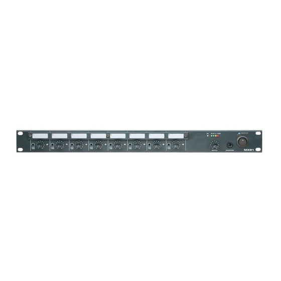
AUSTRALIAN MONITOR MX81 Installatie- en bedieningshandleiding - Pagina 5
Blader online of download pdf Installatie- en bedieningshandleiding voor {categorie_naam} AUSTRALIAN MONITOR MX81. AUSTRALIAN MONITOR MX81 12 pagina's. 8 channel 1 ru mixer
Ook voor AUSTRALIAN MONITOR MX81: Specificaties (2 pagina's)

4
5
6
1
CHANNEL INPUTS
Channels 1 to 6 have two inputs, channels
7-8 only have an XLR input:
XLR input - This is a balanced input.
It accepts mic or line level signals
depending on the front panel gain
switch position. The XLR will also
have +15V phantom power if
selected on the switch.
RCA input - This is an unbalanced line
level input. The two RCA sockets are
summed to mono internally.
2
REC OUT
The REC OUT output is on unbalanced
RCA connectors. The output is dual mono
and is not affected by the MASTER volume
control or the EQ tone controls.
3
OUTPUT
The OUTPUT XLR provides balanced line
level signal.
NOTE: When wiring the LINE
output as unbalanced, Pin2
should be wired as hot and
Pin1 should be wired as
ground/shield. Do not wire Pin3.
4
24VDC SOCKET
This 2.1mm x 5.5mm barrel socket is
provided for 24V emergency systems and
is not switched by the front panel power
switch. Note:The 24VDC socket does not
provide trickle charge facility. Tip of the
connector is positive.
MX81 INSTALLATION & OPERATION MANUAL
3
2
5
IEC MAINS INPUT SOCKET
This is a standard IEC 3 pin socket. It
accepts a standard IEC mains cable,
provided. The fuse draw contains the
mains fuse and a spare. The mains fuse is
a time lag (slow blow) HRC 20mm x 5mm
ceramic type fuse.
The ratings are:
230V/240V model 63mA
115V model 120mA
6
OPTIONAL MODULE INPUTS
This socket is used with a tone module
and/or VCA module.
Always replace the fuse with
one of the same value and type.
NOTE: Always disconnect
power to the amplifier before
replacing fuses.
REAR PANEL
1
PAGE 5
