Bender B91067904W Snelstarthandleiding - Pagina 8
Blader online of download pdf Snelstarthandleiding voor {categorie_naam} Bender B91067904W. Bender B91067904W 12 pagina's. Front panel for isometer® iso685-s variants

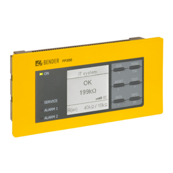
Frontpanel FP200(W)
1. Entfernen Sie die Kontaktabdeckung an der Rückseite
des FP200(W) mit einem Schraubendreher.
2. Entfernen Sie die Kontaktabdeckung an der Rückseite
der ISOMETER® iso685-S Variante.
3. Bringen Sie die drei mitgelieferten Montageclips (2 se-
parat verpackt) manuell oder mittels Werkzeug in der
abgebildeten Position an der Rückseite der ISOMETER®
iso685-S Variante an.
4. Schneiden Sie einen passenden Ausschnitt für das
FP200(W) in Ihrem Schaltschrank aus.
5. Setzen Sie das FP200(W) in den Ausschnitt ein.
6. Montieren Sie die Schraubbefestigung mit einem
Schraubendreher am FP200(W).
7. Klicken Sie das ISOMETER® iso685-S Variante auf die
Hutschiene des FP200(W).
Bedienung
Die Beschreibung der Bedienung und Menüführung fin-
den Sie im Handbuch der entsprechenden ISOMETER®
iso685-S Variante.
Technische Daten
Isolationskoordination (IEC 60664-1/IEC 60664-3)
Bemessungsspannung ..................................................................50 V
Überspannungskategorie (OVC) ........................................................III
Bemessungs-Stoßspannung (IEC 60664-1) ..................................800 V
Bemessungsisolationsspannung (IEC 60664-1) .............................50 V
Verschmutzungsgrad ..........................................................................3
Versorgungsspannung
Versorgungsspannung U
.................................DC 24 V via iso685-S...
s
Eigenverbrauch ............................................................................1,2 W
Anzeige
Grafikdisplay ............................................ 127 x 127 Pixel, 40 x 40 mm
LEDs
ON (Betriebs LED) .......................................................................... grün
SERVICE, ALARM 1, ALARM 2 .........................................................gelb
Schnittstellen
Protokoll ......................................................................... Bender intern
Leitungslänge .............................................................................< 5 m
REMOTE-Leitung ...............................................Patchkabel min. CAT5e
Umwelt/EMV
EMV ................................... IEC 61326-2-4; EN 50121-3-2; EN 50121-4
Umgebungstemperaturen
Arbeitstemperatur ......................................................... -25...+55 °C
Transport ........................................................................ -40...+85 °C
Langzeitlagerung ............................................................ -40...+70 °C
8
FP200_D00169_04_Q_INTE/06.2021
1. Remove the contact cover on the back of the FP200(W)
to expose the contacts.
2. Remove the contact cover on the back of the ISOMETER®
iso685-S variant to expose the contacts.
3. Fix the three mounting clips delivered with the device
(two of them packed separately) manually or using a
tool, as illustrated below at the back side of the
ISOMETER® iso685-S variant.
4. In the cabinet, cut out a section large enough for the
FP200(W) front panel to slide in.
5. Place the FP200(W) into the cutout.
6. Mount the screw attachment to the FP200(W) using a
screwdriver.
7. Click the ISOMETER® iso685-S variant onto the DIN rail
of the FP200(W).
Operation
The description of the operation and menu navigation can
be found in the manual of the corresponding ISOMETER®
iso685-S variant.
Technical data
Insulation co-ordination (IEC 60664-1/IEC 60664-3)
Rated voltge ..................................................................................50 V
Overvoltage category (OVC) ...............................................................III
Rated impulse voltage (IEC 60664-1) ..........................................800 V
Rated insulation voltage (IEC 60664-1) .........................................50 V
Degree of Pollution .............................................................................3
Supply voltage
Supply voltage Us .................................. DC 24 V (via iso685-S variant)
Power consumption .....................................................................1.2 W
Display
Graphic display ........................................ 127 x 127 pixel, 40 x 40 mm
LEDs
ON (operation LED) ......................................................................green
SERVICE, ALARM 1, ALARM 2 ..................................................... yellow
Interfaces
Interface/protocol ........................................................ Internal Bender
Cable length................................................................................≤ 5 m
REMOTE Cable ..............................................Patch cable at least CAT5e
Environment/EMC
EMC .................................... IEC 61326-2-4; EN 50121-3-2; EN 50121-4
Ambient temperatures
Operating temperature .................................................. -25...+55 °C
Transport ........................................................................ -40...+85 °C
Long-term storage ......................................................... -40...+70 °C
