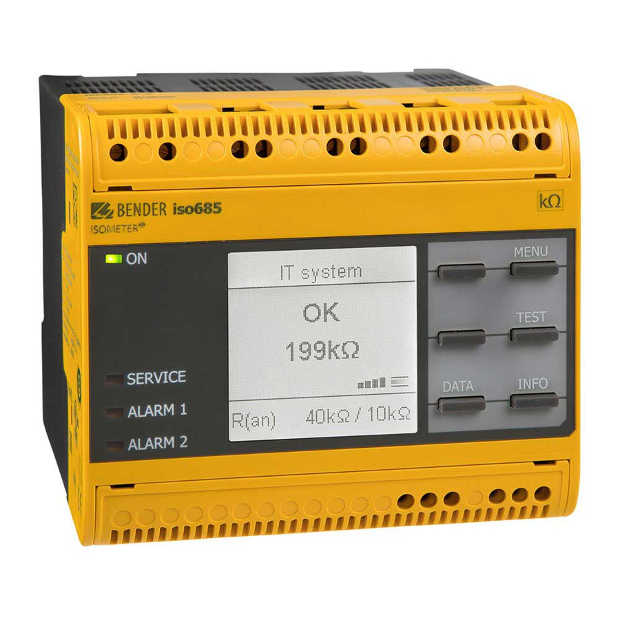
Bender ISOMETER iso685-D-P-CN Snelstarthandleiding
Blader online of download pdf Snelstarthandleiding voor {categorie_naam} Bender ISOMETER iso685-D-P-CN. Bender ISOMETER iso685-D-P-CN 8 pagina's.

快速操作手册 / Quick-start guide
ISOMETER® iso685...-CN
绝缘监视仪
这本快速入门指南适用于下列型号 : iso685-D-CN, W-D-CN,
-S-CN, W-S-CN, D-B-CN, S-B-CN, W-S-B-CN, -D-P-CN, W-D-
P-CN, -S-P-CN, W-S-P-CN. 设备带有 -S 后缀的没有显示, 因
此需要一个外部显示设备。 操作类似于对应的带有显示iso685
变形。
这本快速入门手册不能替代操作手册。你可以在我们的主页
www.bender.de/manuals 上找到操作手册。
m m
1 1 0
使用目的
ISOMETER® 监视不接地交直流主回路(IT 系统)的绝缘电阻,
主回路电压 AC, AC/DC 0...690 V 或 DC 0...1000 V。
出现在 AC/DC 系统中的直流组件不会影响操作特性。 独立的电
源电压允许断开被监视系统。 最大允许的系统泄露电容是1000
µF, 这取决于应用特定的配置。
安全介绍
电击危险 !
端子携带高电压并且直接接触端子可能会导致触
电
如果设备的端子直接连接到通电的 IT 系统 ,
。
危险
端子 E 和 KE 不必从 PE 线断开
由于安装不正确而导致损坏的风险 !
连接多个绝缘监视仪可能会导致安装损坏
如果连接超过一台绝缘监视仪,设备将不起作用,
并不会发出绝缘故障警报
警告
iso685_D00022_06_Q_CNEN/10.2016
1 0 8 m m
。
此外,
。
。
Insulation monitoring device
This quick-start guide applies to the following devices: iso685-D-
CN, W-D-CN, -S-CN, W-S-CN, D-B-CN, S-B-CN, W-S-B-CN, -D-P-CN,
W-D-P-CN, -S-P-CN, W-S-P-CN. Devices with the suffix -S do not
have a display and therefore need an external display. The opera-
tion is similar to the corresponding iso685 variants with display.
This quick-start guide does not replace the operating manual,
which can be found on our homepage under www.bender.de/
manuals.
R(an)
iso685(W)-D, iso685(W)-D-B-CN
PGH ON
Iso.Fehlersuche
Iso.Fehlersuche
43 s
iso685(W)-D-P-CN:
Intended use
The ISOMETER® monitors the insulation resistance of unearthed
AC/DC main circuits (IT systems) with mains voltages of AC, AC/
DC 0...690 V or DC 0...1000 V.
DC components existing in AC/DC systems do not influence the
operating characteristics. A separate supply voltage allows de-
energised systems to be monitored. The maximum permissible
system leakage capacitance is 1000 μF, dependent on the appli-
cation-specific profile.
Safety instructions
Risk of electric shock!
The terminals carry high voltage and direct contact with
these terminals will likely result in electrocution. If the
DANGER
terminals L1/+, L2, L3/- of the device are connected to a
live IT system, the terminals E and KE must not be
disconnected from the protective conductor (PE).
Risk of damage to property due to incorrect
installation!
Connecting more than one insulation monitoring de-
CAUTION
vice may result in damage to the installation. In addi-
tion, the device will not function and will not report an
insulation fault if more than one insulation monitoring
device is connected.
IT System
OK
OK
230 kΩ
230 kΩ
40kΩ/10kΩ
IT-System
1x
1x
1/2
绝缘故障定位 /
insulation fault locati
1
