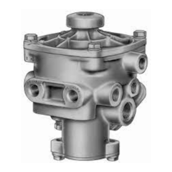
BENDIX RE-4 RELAY EMERGENCY VALVE Handmatig - Pagina 3
Blader online of download pdf Handmatig voor {categorie_naam} BENDIX RE-4 RELAY EMERGENCY VALVE. BENDIX RE-4 RELAY EMERGENCY VALVE 4 pagina's. Relay emergency valve

OPERATING AND LEAKAGE TEST
Check tractor dash air gauge against a test gauge known to
be accurate prior to performing these tests. Connect tractor
air lines to the trailer on which this valve is to be tested.
Block wheels or otherwise hold both vehicles by a means
other than air brakes during these tests.
1. Start these tests with no air pressure in the tractor or
trailer air brake system. Open cut-out cocks, if installed,
and place tractor protection control valve in normal
position. As system pressure ascends and the trailer
emergency line is charged, note that the trailer brakes
are applied. Trailer brake application should completely
release as trailer emergency line pressure reaches
approximately 60-65 psi.
2. Fully charge tractor and trailer air brake systems. Make
several service brake application and check for prompt
braking response at all trailer wheels. With brakes
released and system reservoir pressure stabilized at
90-100 psi, with engine stopped, a two minute check
should result in no more than a six pound pressure drop
for the combination vehicle system. If this check indicates
possible excessive leakage of valve, soap suds should
be applied to cover plate, cover plate vent, and exhaust
port of valve to detect possible inlet valve, inlet valve guide
o-ring and emergency piston o-ring leakage. A combined
leakage as indicated by a 1" soap bubble in not less
than 5 seconds is permissible. No leakage is permissible
at pipe plugs or fittings.
3. Make and hold a full service brake application with system
reservoir pressure stabilized at 100-120 psi with engine
stopped. A two minute check should result in no more
than an eight (8) psi pressure drop for the combination
vehicle system. If this check indicates possible excessive
leakage of valve, soap suds should be applied to cover
plate, cover plate vent, and exhaust port to detect exhaust
valve, valve guide o-ring, emergency piston o-ring and
relay piston o-ring leakage. A combined leakage as
indicated by a 1" soap bubble in not less than 2 seconds
is permissible. Release the service brake application.
4. With tractor and trailer air brake system fully charged,
place the tractor protection control valve to "Emergency"
position or close the supply line cut-out cock on the
tractor and uncouple the trailer emergency line coupling.
Note that trailer brakes apply promptly. Check leakage
at valve, and at the emergency line coupling. Reconnect
and recharge tractor and trailer air brake system, noting
that trailer brakes release at a maximum of 65 psi trailer
emergency line pressure as the trailer air brake system
is recharged to full normal operating pressure.
5. With tractor and trailer air brake system fully charged,
stop engine. Reduce pressure by making a series of
applications and note that trailer brakes apply
automatically at approximately 40 psi tractor reservoir
pressure or at the automatic emergency setting of the
tractor protection equipment, if installed.
REMOVING AND INSTALLING
If the valve does not function as described, or leakage is
excessive, it is recommended that it be replaced with a new
or remanufactured unit or repaired with genuine Bendix parts
available at Bendix outlets.
REMOVING
1. Block trailer wheels.
2. Drain trailer systems air reservoirs.
3. Identify and disconnect air lines from valve. (Note: the
emergency piston and valve assembly, generally referred
to as the "insert" can be removed without line removal.
To remove the insert, remove cover plate and pull insert
out.)
4. Remove mounting bolts, then valve.
INSTALLING
If valve will be flange mounted directly to steel, it is
recommended that a flange gasket be utilized to prevent
electrolytic action between the unlike metals.
If the valve is adapter or nipple mounted directly to a reservoir,
it is recommended that "Never Seez" lubricant be applied to
the threads before installation. This will prevent galling of
the threads and make removal easier.
1. Clean and inspect all connecting lines and hoses for
cracks, deterioration or damage. Replace as necessary.
2. Mount valve securely.
3. Connect all lines and hoses to valve.
DISASSEMBLY
1. Remove capscrews, lockwasher, then cover plate and
emergency spring (1) from bottom of valve.
2. Remove insert (5) through bottom of valve (keep insert
centered during removal to avoid damage to exhaust
valve.
(Note: If new insert is to be installed omit steps 3-8).
3. Remove three o-rings (2) (3) & (4) from insert.
4. Using wrench flats provided, remove emergency piston
cap nut (6) from emergency piston (5). Use care to avoid
damaging finished diameters.
5. Remove valve spring (7) and emergency piston cap nut
o-ring (8).
6. Remove Phillips head screw, lockwasher and exhaust
valve (9) from inlet valve body (10).
7. Remove inlet body from emergency piston.
8. Remove inlet valve o-ring (12) from inlet valve body. Mark
cover and body to assure proper positioning when
assembling.
9. Remove capscrews, lockwashers then top cover (11) from
body. Remove o-ring (13) from cover.
10. Remove relay piston (14) and piston return spring (15)
from body.
11. Remove screw from exhaust cover (16) and remove
exhaust diaphragm (17).
12. Remove seal ring (18) and o-ring (19) from relay piston.
3
