5G HUB BG77 Technisch handboek en gebruikershandleiding - Pagina 13
Blader online of download pdf Technisch handboek en gebruikershandleiding voor {categorie_naam} 5G HUB BG77. 5G HUB BG77 14 pagina's. 5g nb-iot & gnss usb kit
Cortex Debug
Connector
ADC0
ADC1
GPIO26
GPIO64
SPI
USIM
USB Boot
Precaution
The USB dongle runs at 3.3V. The maximum voltage that the I/O pins can tolerate is 3.3V.
Applying voltages higher than 3.3V to any I/O pin could damage the board
2.9 BG77 chipset
All functionality of the BG77 shipset shall be implemented excluding the following features. That is, the
following features are not supported [1][2].
-
Audio, Earphone, and Codes are not supported.
-
PCM and I
2
C are not supported
-
PSM_IND and AP_READY are not supported
2.10 Interface between SAM21D and BG77
The Microcontroller communicates with the BG77 through UART interfaces:
-
UART1: (PA12/PA13/PA14/PA15). Used for data transmission and AT command communication
115200bps by default. The default frame format is 8N1 (8 data bits, no parity, 1 stop bit) Support
RTS and CTS hardware flow control.
UART3: (PB23/PB22). Used for outputting GNSS data or NEMA sentences 115200bps baud rate.
-
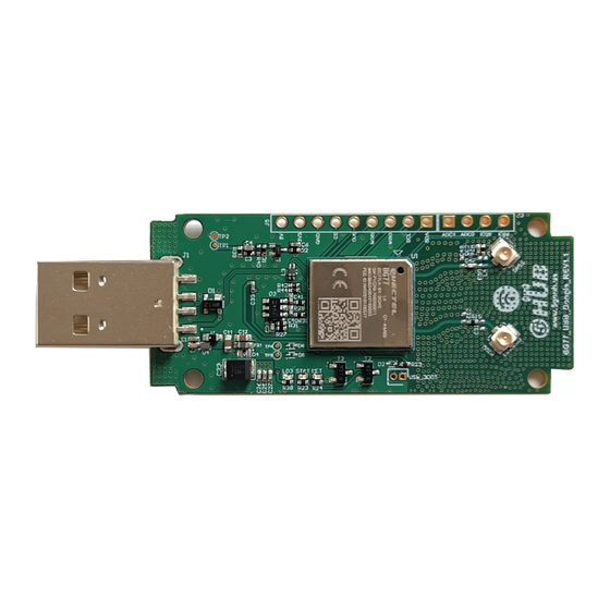
USB Dongle Rev 1.0
Using Single Wire Debug to burn bootloader and debug the
IO
board
I
Connected to BG77. General purpose analogue to digital converter
I
Connected to BG77. General purpose analogue to digital converter
IO
Connected to BG77. General purpose IO
IO
Connected to BG77. General purpose IO
IO
Connected to BG77.
I
Used to insert a Nano USIM. Connected to BG77
Connected to BG77. Force the BG77 to enter emergency download
I
mode
Copyright © 5GHUB.US
13