Hi-Force HAP21014 Series Gebruiksaanwijzing - Pagina 7
Blader online of download pdf Gebruiksaanwijzing voor {categorie_naam} Hi-Force HAP21014 Series. Hi-Force HAP21014 Series 8 pagina's. Air driven hydraulic pumps
Ook voor Hi-Force HAP21014 Series: Gebruiksaanwijzing (8 pagina's)
INSTRUCTION MANUAL – AIR DRIVEN HYDRAULIC PUMPS:
Model Series: AHP1120, AHP1120R, AHP1121, AHP1121R, AHP1122, AHP1122R, AHP1141, AHP1142,
HAP21011, HAP21012, HAP21014, HAP21016, HAP21021, HAP21022, HAP21024, HAP21026, HAP21031,
HAP21032, HAP21034, HAP21036, HAP21041, HAP21042, HAP21044, HAP21046,
under the skin see a doctor
immediately.
Never pressurise uncoupled couplers.
●
Always use eye, ear and hand
●
protective equipment when using this
pump and associated equipment
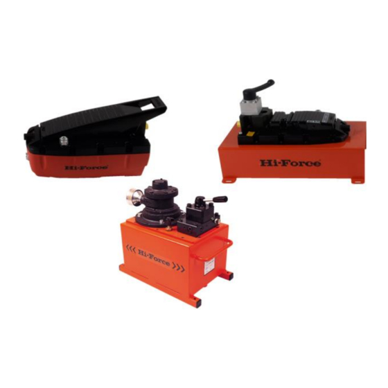
10.0 Identification of Components.
Refer to diagrams on following pages.
1.
Oil reservoir
2.
Hydraulic Oil level gauge
3.
Oil filler breather cap
4.
Motor
5.
Silencer
6.
Adjustable pressure relief valve
7.
Hydraulic directional control valve – if
fitted (type will vary)
8.
Hydraulic service connections
9.
Hydraulic oil drain plug
10. Roll frame (optional)
11. Motor air inlet.
Hi‐Force Limited – Prospect Way – Daventry – Northants NN11 8PL – United Kingdom
Tel: +44(0) 1327 301000: Fax: +44(0) 1327 706555: Website: www.hi‐force.com
11.0 Preparing the Pump for first use:
1.
Immediately after unpacking, examine
the pump for signs of transit damage
and if found contact the shipping
company.
2.
Establish the oil level in the oil reservoir
using the level gauge on the end of
the tank. Depending on the shipping
method used, the reservoir may either
be supplied full or empty. If the
reservoir is empty it must be correctly
filled before use. Remove the
temporary transit plate which is fitted in
the position of the filler breather cap
(3) by undoing the 3 screws. Fit the filler
breather cap (packed separately)
using the 3 screws which held the
transit plate.
3.
To fill the reservoir: Remove the filler
cap (3) and fill the tank with clean
HFO46 oil to the upper level indicator
(2).
4.
Connect the air supply to the Motor air
inlet (11). Max inlet pressure 7 bar. It is
recommended that a filter and
lubricator are incorporated in the air
supply.
5.
Ensure your air supply circuit includes a
ball or sliding valve close at hand,
which can be used to control the air
supply.
6.
Remove hexagon headed plugs and
make hydraulic connections to service
ports (8).These ports have a 3/8" NPT
female thread and the corresponding
male connections should be wrapped
with PTFE tape or other suitable
sealant.
7.
Ensure the lever of the hydraulic
directional control valve (7) is in the
neutral position. This is fully
anticlockwise for models with 2 way
valve (HAP21021, HAP21022, HAP21024,