Dynabrade 52861 Handmatig - Pagina 5
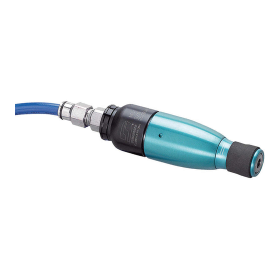
Blader online of download pdf Handmatig voor {categorie_naam} Dynabrade 52861. Dynabrade 52861 8 pagina's. 25,000 rpm pencil grinder

Disassembly/Assembly Instructions – 25,000 RPM Pencil Grinder
Important: Manufacture warranty is void if tool is disassembled before warranty expires by anyone other than a Dynabrade authorized repair technician.
Notice: All of the special tooling referred to in these instructions can be ordered from your Dynabrade Distributor. Please refer to this parts page
for correct part identification. Before servicing this air tool always shut off the air supply valve and dissipate the remaining air pressure before
disconnecting the tool from the air supply.
Valve Disassembly:
1. Remove the collet cover with grip from the 52885 Housing by turning it counterclockwise.
2. Use the 96076 Wrench (12mm) to hold the 01435 Collet Body stationary while using the 95262 Wrench (14mm) to remove the 01484 Collet Cap by
turning it counterclockwise.
3. Place the 52296 Repair Collar around the thickest portion of the 52885 Housing.
4. Fasten the tool with the repair collar into a vise so that the collet body is pointing down.
5. Use two wrenches, one to hold the 01494 Inlet Bushing stationary, and one to remove the 96229 Male Fitting from the inlet bushing. Turn
the fitting counterclockwise.
6. Use a wrench to remove the 01494 Inlet Bushing by turning it counterclockwise.
7. Remove the 52880 Cover Retainer, cover, and 52882 Felt Muffler.
8. Remove the 01468 Spring, 58365 Tip Valve, 01464 Seal, and 52876 Valve Stem.
Valve Disassembly Complete.
Access Air Motor:
1. Remove the 96016 O-Ring.
2. Use a HOT AIR GUN to apply heat to the 52875 Twist Valve Manifold.
3. Use an adjustable wrench to remove the twist valve manifold from the 52885 Housing by turning it counterclockwise.
4. Remove the 52872 Air Inlet Gasket from the twist valve manifold.
5. Push the air motor assembly out of the 52885 Housing.
Air Motor Disassembly:
1. Fasten the 96346 2" Bearing Separator around the portion of the 01476 Cylinder that is closest to the 52871 Rear Bearing Plate. Place the bearing
separator on the table of the 96232 #2 Arbor Press so that the collet body is pointing down. Use a 3/16" or 5mm diameter flat end drive punch as a
press tool and push the rotor out of the 02696 Bearing. Use the 96210 Bearing Removal Tool and the arbor press to remove the 02696 Bearing from
the rear bearing plate.
2. Fasten the vane slot portion of the rotor in a vise with aluminum or bronze jaws so that the collet body is pointing up.
3. Use an adjustable wrench to remove the collet body by turning it counterclockwise.
4. Remove the front bearing/plate/shims and the 01479 Spacer.
Air Motor Disassembly Complete.
Air Motor Assembly:
1. Install the 01479 Spacer onto the rotor.
2. Select .003" (.08mm) thickness shims from the 54529 Shim Pack and install these into the 02038 Front Bearing Plate.
3. Install the 02649 Bearing into the front bearing plate.
4. Position the rotor in a vise with aluminum or bronze jaws so that the rotor spindle is pointing up. Install the front bearing/plate/shims onto the rotor.
5. Install the 01435 Collet Body onto the rotor. (Torque to 17N·m/150 in. lbs.)
6. Remove the assembly from the vise.
7. Use a .001" (0.3mm) thick feeler gauge to check the clearance between the front bearing plate and the face of the rotor. The clearance should
be .001"-.0015" (0.3-0.4mm). Note: If the clearance needs adjustment repeat steps 2-6, adding or removing shims as required.
8. Lubricate the 01480 Vanes (4) with the 95842 Dynabrade Air Lube 10W/NR (or equivalent) and install these into the rotor.
9. Install the 01476 Cylinder over the rotor so that the air inlet opening of the cylinder will line up with the air inlet opening in the 52871 Rear Bearing Plate.
10. Use the raised outer diameter of the 96216 Bearing Press Tool and the 94232 #2 Arbor Press to install the 02696 Bearing into the
52871 Rear Bearing Plate.
11. Use the raised inner diameter of the 96216 Bearing Press Tool and the arbor press to install the rear bearing/plate onto the rotor.
Note: Carefully press the bearing/plate down until it just touches the cylinder. This will establish a snug fit between the bearing plates and the cylinder.
12. Install the 52872 Air Inlet Gasket into the twist valve manifold carefully so that the air inlet is completely open.
13. After threaded surfaces have been properly cleaned and primed, apply a small amount of the Loctite
Valve Manifold.
14. Position the air motor so that the 52871 Rear Bearing Plate fits into the 52875 Twist Valve Manifold.
15. Carefully slide the motor assembly into the 52885 Housing and thread the twist valve manifold into the housing.
(Torque to 17N·m/150 in. lbs.)
16. Install the 96016 O-Ring onto the 52875 Twist Valve Manifold.
Air Motor Assembly Complete.
Valve Assembly:
1. Position the tool with the 52296 Repair Collar in a vise so that the opening for the 52876 Valve Stem is facing up.
2. Install the 52876 Valve Stem along with the 98459 O-Ring into the 52875 Twist Valve Manifold.
3. Install the 52882 Felt Muffler into the deep curved recess in the cover and carefully slide the cover onto the twist valve manifold.
4. Position the tool with the 52296 Repair Collar in a vise so that the air inlet opening is facing up.
®
#567 to the external threads of the 52875 Twist
(continued on next page)
