Hi-Velocity RPM-E-100 Installatiehandleiding - Pagina 2
Blader online of download pdf Installatiehandleiding voor {categorie_naam} Hi-Velocity RPM-E-100. Hi-Velocity RPM-E-100 6 pagina's.
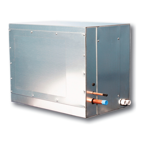
Refrigerant Modules (RPM-E)
The RPM-E series cooling module can be used with the Hi-
Velocity Fancoil, installed in many different positions. It is pre-
piped with an adjustable, heat pump ready, thermal expansion
valve and comes with a bleed port, sight glass, suction and liquid
line access ports, freeze-stat, and two L brackets for mounting.
The RPM-E comes as a complete module and must be installed
in the vertical position on the return air side of the fancoil; the
unit cannot be turned on its side and is a draw through unit
only. The module offers multi-position airflow configurations
for horizontal, highboy, or counter-flow configurations. (Fig.
RPM-01)
The TXV (Thermal Expansion Valve), sight glass, access
ports, and freeze-stat* are already installed and are accessible
through an easy to remove access hatch. The liquid and suction
lines have male solder connections at a standard width making
connections to the condenser lines quick and easy.
*IMPORTANT:
The freeze control serves the
purpose of preventing severe icing of the coil in the
event of an undercharge or low load on the coil. This
piece of equipment must be used at all times. Lack
of use of the freeze-stat will result in RPM-E related
warranty issues being voided.
Configurations
When installing, follow the recommendations shown in
Table 01, demonstrated in Fig. 01. For example, a horizontal
application could use A to B while highboy applications could
use A to B1. Do not use a combination of A to A1 or B to B1,
as this would bypass the cooling coil completely. A1 is not
to be used for outlet airflow. The knock-outs can be removed
with a screw driver and hammer. Use caution when opening
the knock-outs, ensuring you do not damage the coil surface.
Table RPM-01 - RPM-E Cooling Module Configurations
Right
A to B
A to B1
A1 to B
A1 to B1
B to A*
B1 to A*
*B to A and B1 to A configurations are not recommended,
due to a higher chance of carry-over issues.
Important: If side A1 is going to be used in your selected
configuration, the extended drain pan must be removed.
www.hi-velocity.com
Wrong
B1 to A1
B to A1
A to A1
B to B1
Module RPM Refrigerant Module Installation (RPM-E) (1/5)
Refrigerant Module Installation (RPM-E) (1/5)
Fig. RPM-01 - RPM-E Cooling Module Configurations
B1
A
A1
Rough Opening Sizes
RPM-E 50
RPM-E-70
RPM-E-100
RPM-E Drain Pan Extension
The RPM-E Drain Pan Extension (DPE) is to be removed for
up flow (vertical) return air applications (avoid installing the
RPM-E in counter flow applications).
To remove the pre-installed DPE, first remove left side access
panel of the RPM-E Module. Remove the 3 - ¼ " screws
that hold the DPE in place, remove the DPE and replace ¼"
screws into the coil support (Fig. RPM-02). Replace the left
side access panel.
Fig-RPM-02 - Remove DPE
The lower knockout can now be removed, using a screwdriver
and hammer (Fig-RPM-03). Use caution when removing
knockouts ensuring you do not damage the coil inside the
module.
Fig-RPM-03 - Remove Knockout
Module RPM
B
A or B
A1 or B1
11
"L X 13
"H
11
"L X 9"W
3/4
1/4
3/4
(298mm X 337mm)
(298mm X 229mm)
16
"L X 13
"H
16
"L X 9"W
3/4
1/4
3/4
(425mm X 337mm)
(425mm X 229mm)
22
"L X 13
"H
22
"L X 9"W
3/4
1/4
3/4
(578mm X 337mm)
(578mm X 229mm)
© 1995-2009 Energy Saving Products Ltd.
© 1995-2013 Energy Saving Products Ltd.