Hi-Velocity RPM-E-50 Installatiehandleiding - Pagina 3
Blader online of download pdf Installatiehandleiding voor {categorie_naam} Hi-Velocity RPM-E-50. Hi-Velocity RPM-E-50 6 pagina's.
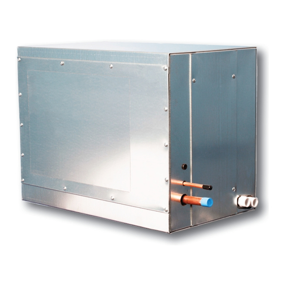
Mounting the RPM-E
Two L mounting brackets are shipped loose for attaching the
RPM-E to the fancoil, along with two sided foam tape for an
air seal between the units. When mounting the cooling coil to
the fancoil (Fig. RPM-04), ensure that no screws puncture the
drain pan or coil. It is advised that no screws be placed within
3 inches
from the bottom of the coil. This will prevent
(76mm)
the drain pan from being accidentally pierced. It is also advised
that care be taken when placing screws in the top left side of
the cooling coil (when looking at the access hatch), as this is
where the top most extent of the cooling coil is located. See
Specification Pages
for the dimensions of the fan coil units and
cooling modules.
Fig. RPM-04 - Mounting Brackets
(76mm)
(76mm)
Secondary Drain Pan
Some building codes call for the use of a secondary drain pan
underneath the entire unit (Fig. RPM-05). Any installation that
has the potential of property damage due to condensate must
have a secondary drain pan installed. If the unit is installed in a
high heat and/or high humidity location, extra insulation around
the unit casing may be required. This will prevent excessive
condensate from forming on the outer surface of the casing.
www.hi-velocity.com
(76mm)
(76mm)
Module RPM Refrigerant Module Installation (RPM-E) (2/5)
Refrigerant Module Installation (RPM-E) (2/5)
Fig. RPM-05 - Secondary drain pan
Secondary drain pan
Drain Connections
All RPM-E modules come with a ¾"
secondary outlet. The condensate drain must have a vented p-trap
installed (Fig. RPM-05), and run at a slope of ¼"
foot in the direction of the drain. When installing the P-trap, one
must be installed on both the primary and secondary outlets. The
P-traps must have a minimum depth of two inches
to the high negative pressure of the blower system, the RPM-E
will hold some amount of water during operation. Once this level
has been achieved, condensate will flow from the coil regularly.
When the unit shuts down, or lowers speed, the force is released,
allowing the held condensate to empty from the drain pan.
During this time, condensate may flow from both the primary
AND secondary drains.
Outdoor Unit Installation
Locate the outdoor unit in a suitable location, as close as
possible to the fan coil. Maintain the clearances recommended by
the manufacturers of the outdoor unit, to ensure proper airflow.
The outdoor unit must be installed level, in a properly supported
location. A liquid line filter/drier is recommended to be installed.
Wiring - Outdoor Unit
Make all connections to the outdoor unit with rain tight conduit
and fittings. Most building codes require a rain tight disconnect
switch at the outdoor unit as well (always check local codes).
Run the proper size copper wires to the unit, and connect as per
the manufacturer's recommendations.
Ensure that the outdoor unit is setup for a TX system. If not, a
hard start kit may be required.
Module RPM
P-Trap
primary and
(19mm)
per
(6.7mm)
. Due
(51mm)
© 1995-2009 Energy Saving Products Ltd.