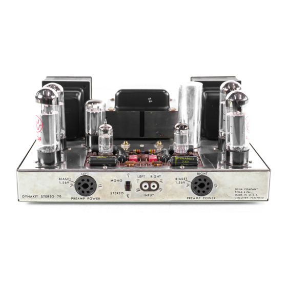
DYNACO Stereo 70 Instructies voor montage - Pagina 12
Blader online of download pdf Instructies voor montage voor {categorie_naam} DYNACO Stereo 70. DYNACO Stereo 70 16 pagina's. Series ii tube amplifier
Ook voor DYNACO Stereo 70: Restauratie Handboek (20 pagina's), Restauratie Handboek (5 pagina's), Gebruikershandleiding (12 pagina's)

actual value of negative voltage will depend on the
setting of the respective bias potentiometer. With
the Biaset con n e c t ion reading the proper 1.56
volts, the negative voltage at the EL-34 tubes
should be within 20% of minus 32 volts.
If
the two
tubes in a pair have different negative voltages
at pin #5, as measured by a VTVM, this is a clue
to
a
defective component or wiring.
(V2 and V3
make one pair; V6 and V7 make the other pair).
A small difference in voltage indicates either a
runaway tube (which can be checked by borrowing
the pair from the other channel) or a leaking .1
mfd capacitor on the PC-3 board.
If
one tube has
no negative voltage, it indicates that there is an
open connection from the bias supply to this tube.
If
no meter is available, it is possible to pin
down the fault with a glowing tube by switching the
two tubes of the pair.
In
the same socket exhibits
the glow, the fault is in the amplifier bias supply
or components.
If
the same tube glows in trans-
posed position, it is most
like~a
defective tube.
The tubes sup
P
lie d with the Stereo 70 are
matched and should be completely interchangeable.
When making replacements of tubes, they should
preferably (although not absolutely essential) be
replaced in pairs which are matched.
There is
no need to maintain matching of all four EL-34
tubes.
In emergencies, substitution of the tubes can
be made with at her tube types.
The 5881 and
KT -66
can be used in place of the EL-34's provided
the bias is readjusted to give 1.56 at the Biaset
check point. The 5U4G or 5U4GB can be used in
place of the GZ -34. There is no substitute for the
7199 tube.
No signal
If
there is no signal coming through the ampli-
fier, each side should be checked separately to
see whether one channel may be working.
If
one
works, and the other does not, the working channel
can be used for test purposes.
For example, the
tubes can be interchanged to determine whether
they will work in eithe r channel.
In
this way, a
defective tube can be singled out.
It
is advisable to remove the input cable and
see whether insertion of the plug makes a "thump"
through the loudspeaker.
Sometimes, a defective
cable or pre amp prevents signal from coming
through while the amplifier itself is operative.
If
there is no signal from the preamplifier, but a
"thump" can be induced by unplugging the shielded
cable from the preamplifier or by inserting the tip
of a small screwdriver into the input socket, then
the fault is not in the amplifier but in the associated
equipment.
If
a meter is available, voltages should be
checked in comparison with the voltage table in-
10
eluded in these instructions.
Departures of more
than 10% from the values shown indicate possible
malfunctioning of some of the circuit components.
Hum and noise
If
excessive hum or noise appear, it is neces-
sary to determine whether they occur within the
amplifier. Sometimes noise in the preamplifier is
blamed on the amplifier.
The simple test is to
remOve the cables from the input socket and see
whether the same noise is present. If the noise is
removed when the cable is unplugged, it is in the
preceding equipment which should then be checked.
If
not, it is probably in the amplifier.
Compare the noise in the two channels.
If
both are the same, it is not likely to be tubes like
the 7199 or EL-34 which affect only the channel
in
which they operate, but it could be the GZ-34 or
the quad capacitor or bias capacitors which are
common to both sides of the circuit.
Sizzling sounds coming through the loudspeaker
may come from poor can t act s between circuit
elements and chassis.
Make sure that ground
connections are tight.
In
some rare cases, loud pops may be heard
through the loudspeakers. These can come from
poor conditions inside the pins of the EL-34 tubes.
Touching a hot soldering iron to these pins will
rectify this. Make sure that solder is not deposited
on the pin or the tube may not fit the socket.
In
the event that trouble shooting will not cor-
rect the problem, factory consultation is available
without charge, and factory service at moderate
charge.
FACTORY SERVICE AND GUARANTEE
The Dynakit Stereo 70 is designed to provide
good service over a long period of time.
It is
intended to be used at the conventional 117 volt
line input found
in
most homes.
Operation up to
125 volts will not cause any problem. Above that
voltage, it is suggested that a voltage regulating or
adjusting device be used
in
order to protect the
components
in
your amplifier. The normal guar-
antee on the equipment is not applicable
if
it is
used above the 125 volt rating.
All parts in the Stereo 70 are guaranteed for a
period of one year from purchase except tubes
which carry the standard EIA guarantee of 90 days.
Parts which are defective will be replaced at no
charge if they are returned prepaid to the factory
either directly or via the dealer from whom the kit
is purchased. Many Dynaco dealers carry spare
parts
in
stock to facilitate replacements.
After
the guarantee period is past, Dynaco will supply
any non-standard parts used at net prices. Parts
