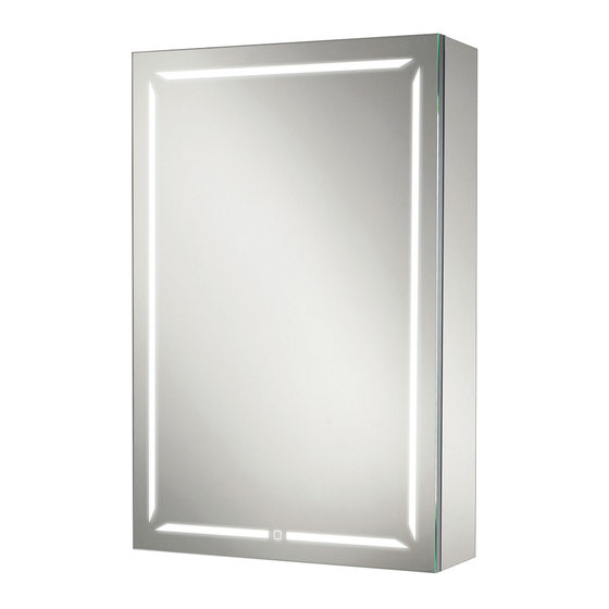
HiB Groove 80 Montage-instructies - Pagina 2
Blader online of download pdf Montage-instructies voor {categorie_naam} HiB Groove 80. HiB Groove 80 4 pagina's. Bluetooth cabinets
Ook voor HiB Groove 80: Handmatig (2 pagina's)
REAR VIEW
Mounting Points
Location of internal
xing hole (SINGLE DOOR)
Location of internal
xing hole (DOUBLE DOOR)
Fixing Preparation (Fig A)
Fixing Brackets (Fig B)
Wall Hung Installation
Ensure the domestic electrical mains supply to which
the cabinet is being connected is turned off.
1.
Position the cabinet in a suitable location
(according to the zonal diagram (Fig 1) on the
back page) ensuring that the mains supply cable is
within reach of the cable connection point of the
cabinet. Carefully mark the desired position of the
cabinet using a soft pencil, ensuring it is level.
2.
Remove the cabinet from the wall and using a
spirit level, mark a horizontal line below the pencil
mark, taking into account the location of the
mounting points (Fig. A). Place brackets on the
line paying attention to the distance between the
hangers on the cabinet. Carefully mark the position
of the holes using a soft pencil. (Fig. B).
3.
Before drilling, ensure there are no hidden cables
or pipes behind the mounting point. Using a
suitable drill bit, drill holes in the marked positions
to a suitable depth.
4.
Insert wall plugs level with the surface of the wall.
If fitting to a tiled surface, wall plugs should be
inserted below the tile surface to avoid cracking.
NB. For plasterboard walls, specialist fixings should be
purchased from any DIY or hardware store.
5.
Fix the brackets to the wall using the screws
provided.
6.
Carefully remove the small screws along the top
front edge of the cabinet to gain access to the
internal panel(s). (Fig. C) Keep screws in a safe
place.
7.
Temporarily hang the cabinet ensuring the claws
on the hangers are securely located on the wall
brackets. Using a spirit level adjust the cabinet via
the screws on the hangers. (Fig. C).
8.
Mark the position of the internal fixing hole and
remove the cabinet. Using a suitable drill bit, drill a
2
Hanger Adjustment (Fig C)
hole and insert a wall plug as per stage 4 above.
9.
Connect the cable at the rear of the cabinet to the
mains supply cable using a suitable terminal block
(not supplied) according to the wiring diagram (Fig.
2) on the back page.
10. Rehang the cabinet in position, tighten the screws
on the hangers (Fig. C) and secure the base of the
Move door(s) up/down
cabinet with the supplied screw(s) and screw cap(s).
11. Switch the mains supply back on.
Move door away/towards
Move door(s) up/down
the cabinet
Move door(s) left/right
Move door away/towards
the cabinet
Move door(s) left/right
Door Adjustment (Fig D)
Operation Instructions
To turn illumination on, touch the sensor once (Fig.E).
To change the colour temperature, touch and hold the
sensor until desired colour is obtained. The colour temp
is then set until changed again.
Heated Pad is only on when cabinet is illuminated.
Angle Adjustment
Claw In/Out
Claw In/Out
Adjustment
Adjustment
Move door(s) up/down
Move door away/towards
the cabinet
Move door(s) left/right
Move door(s) up/down
Move door away/towards
the cabinet
Move door(s) left/right