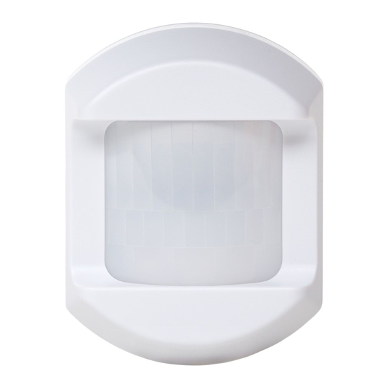
2gig Technologies pir1-345 Installatie-instructie - Pagina 3
Blader online of download pdf Installatie-instructie voor {categorie_naam} 2gig Technologies pir1-345. 2gig Technologies pir1-345 4 pagina's. Passive infrared motion detector

Environmental and Other Useful Information
While the PIR is a highly reliable intrusion detection device, it does
not guarantee against burglary. Any intrusion device is subject to a
"failure to warn" for a variety of reasons. Consider the following
when installing and setting up the PIR:
This PIR has built‐in protection to keep bugs from getting into
1
the sensor area and causing false alarms. Note that this
protection does not prevent insects from crawling across the
lens of the PIR, which could trigger the PIR.
Infrared energy can be reflected off any glossy surfaces such as
2
mirrors, windows, floors, or counter tops with glossy finish, and
slick‐finished concrete. Some surfaces reflect less than others
(e.g. the PIR can see a change in infrared energy off of reflective
surfaces even if the heat or cold source is not within the PIR
detection pattern).
Windows reflect infrared energy. They also allow sunlight or
3
light from other sources (e.g., cars) to pass through to the PIR.
The PIR can detect these changes in infrared energy. For
example, if sunlight passing through a window shines onto a
hardwood floor and the change in infrared energy is quick
enough, the PIR can trigger an alarm. The same applies if the
PIR area includes a window, even though the pattern of
protection cannot "see" through glass. Lights from a passing car
can also pass through the window at night and shine directly
into the PIR's lens.
4
Heating and air conditioning ducts are also important because if
they blow air onto an object within the field of the PIR's view,
the temperature of that object could change quickly enough for
the PIR to "see" a change in infrared energy. PIR's cannot see air
current, only the change in temperature of a physical object.
The PIR senses change in temperature. However, as the ambient
5
temperature of the protected area approaches the temperature
range of 95° to 120° F, the detection performance of the PIR
decreases.
Ensure that the area you wish the PIR to cover is free of
6
obstructions (for example, curtains, screens, plants, and so on.)
that may block the pattern of coverage.
7
Anything that can sway or move due to air current can cause a
change in infrared energy within the fields of view. Drafts from
doors or windows can cause this to happen. Plants, balloons,
curtains, and hanging baskets should never be left in the PIR's
field of view.
8
Do not mount the PIR on a surface that allows for any vibration.
Vibrations not only cause the PIR to move a little, but it also
causes the fields of view in a room to move with respect the PIR.
A little vibration can cause havoc with the PIR's field of view,
thus the PIR may see a change in energy and trigger the alarm.
An installation often requires that the PIR is aimed at the door.
9
The PIR may detect door movement before the door contact
can initiate an entry delay, causing the alarm to trigger. If you
install the PIR facing a door, then while programming the PIR,
choose an appropriate sensor/zone type.
The PIR ONLY detects intrusion within the pattern of coverage.
10
The PIR does not provide volumetric area protection.
11
12
The PIR creates multiple beams of protection. Intrusion can only
be detected in unobstructed areas covered by those beams.
13
The PIR cannot detect motion or intrusion that occurs behind
walls, ceilings, floors, closed doors, partitions, glass doors, or
windows.
Tampering with, masking, painting, or spraying of any material
14
on the PIR lens or any part of the optical system can impair
detection ability.
Passive Infrared Motion Detector | Installation Instructions
The PIR, like other electrical devices, are subject to component
15
failure. Even though the PIR is designed to last as long as 10
years, the electronic components are subject to failure.
Lens Pattern and Tilt Angles
The diagrams below show the lens pattern and tilt angles for the PIR
in meters.
Figure 5 Lens Pattern—Top View
Figure 6 Tilt Angle—Side View
‐9°
PIR titled down one click
0°
PIR facing the opposite wall (Direct‐to‐wall or mounting bracket with no
tilt adjustment.
‐18°
PIR tilted down two clicks
+9°
PIR tilted up one click
Copyright © 2014 Linear LLC
3
