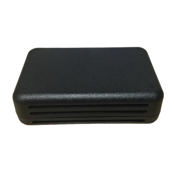
Automation Components WT2630AR/P Installatie- en bedieningsinstructies
Blader online of download pdf Installatie- en bedieningsinstructies voor {categorie_naam} Automation Components WT2630AR/P. Automation Components WT2630AR/P 3 pagina's. Humidity and temperature wall sensor series

HUMIDITY AND TEMPERATURE
WALL SENSOR SERIES
Installation & Operation Instructions
WH2630AR/P, WT2630AR/P
GENERAL INFORMATION
The WH2630 and WT2630 are battery operated spread
spectrum wireless wall humidity temperature sensors
housed in a rugged enclosure.
ACI's mesh network Series 2000 wireless sensors utilize
reliable Spread Spectrum Radio technology. They can be
installed easily in minutes eliminating hundreds of feet of
wire and saving installation cost while reducing installation
labor risks.
The Series 2000 sensor Data-Link LED con rms the data
transmission was received by the receiver for fast and
reliable positioning of the sensor during installation. There
is no need for special wireless installation equipment or
tool.
Together with the ACI Series 2000 receivers and controllers,
the ACI wireless sensors can be used with any LON, BacNet,
MODbus, or DDC control system or panel.
The maximum radio transmission distance is dependent on
the building type. The maximum open air transmission
distance is one mile. In a typical commercial building with
steel I-Beam construction, concrete oors with reinforcing
rod, and metal stud walls, it can be expected that
transmissions will penetrate vertically through oors and
horizontally through 200 to 300 feet of walls, furniture and
air.
MOUNTING INSTRUCTIONS
Wireless sensors should be installed within 200 to 300 feet of
the receiver. RR2552 signal repeaters can be installed as to
increase transmission distance between sensors and receivers.
WIRING INSTRUCTIONS
To select the proper sensor location, rst install and power the receiver. To activate the sensor insert the
battery observing the polarity. The mesh networked Series 2000 system does not require any additional
wireless equipment to determine the proper location of the sensors.
While the sensor is attempting to connect to the receiver the Data-Link LED will blink rapidly 8–10 times
every 10 seconds. Once a connection has been established the Data-Link LED will blink once to indicate
the data transmission has been received successfully. The Data-Link LED will continue to blink once for
every data transmission. The data transmission rate is programmed into the sensor (normally 1 minute
intervals). To manually initiate a data transmission press the push button switch located by the negative
terminal of the battery.
Automation Components, Inc.
2305 Pleasant View Road | Middleton, WI 53562
Phone: 1-888-967-5224 | Website: workaci.com
FIGURE 1: DIMENSIONS
2.625"
(66.68mm)
Page 1
Phone: 1-888-967-5224
Website: workaci.com
4.25"
(107.95mm)
1.26"
(32mm)
External
Link Button
Top View
Version: 5.0
I0000685
1.26"
(32mm)
