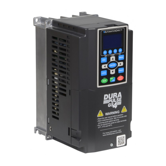
Automation Direct DURApulse GS4 Snelstarthandleiding - Pagina 7
Blader online of download pdf Snelstarthandleiding voor {categorie_naam} Automation Direct DURApulse GS4. Automation Direct DURApulse GS4 9 pagina's. Ac drive

DURApulse GS4 AC Drive Quick-Start Guide
Specifications for Wiring Terminals – Main-Circuit Terminals (continued)
Max Wire
Min Wire
Torque
Drive Models
Note
Gauge
Gauge
(±10%)
For models without conduit box
UL installations must use 600V, 75°C or 90°C wire.
1/0 AWG*2
Please use copper wire only.
GS4-2060
(53.5 mm
2
*2)
(Fig. 1) The usage of ring terminals should comply
3/0 AWG*2
GS4-2075
(85 mm
2
*2)
(Fig. 2) Grounding wire specification:
300 MCM*2
4/0 AWG*2
GS4-2100
(152 mm
2
*2)
(107 mm
2
*2)
1/0 AWG*2
(Fig. 3) The figure shows the specification of insulated
GS4-4125
(53.5 mm
2
*2)
3/0 AWG*2
GS4-4150
(85 mm
2
*2)
Figure 1:
M8
For models with conduit box
200 kg·cm
1/0 AWG*2
(173 lb·in)
GS4-2060
(53.5 mm
2
*2)
(19.62 N·m)
2/0 AWG*2
GS4-2075
(67.4 mm
*2)
2
4/0 AWG*2
3/0 AWG*2
Figure 3:
GS4-2100
(107 mm
2
*2)
(85 mm
2
*2)
1/0 AWG*2
GS4-4125
(53.5 mm
2
*2)
2/0 AWG*2
GS4-4150
(67.4 mm
2
*2)
UL installations must use 600V, 75°C or 90°C wire.
For models without conduit box
Please use copper wire only.
4/0 AWG*2
GS4-4175
Grounding wire specification:
(107 mm
2
*2)
300 MCM*2
300MCM*2 [152 mm
(152 mm
2
*2)
300 MCM*2
(Fig. 1) The usage of ring terminals should comply
GS4-4200
(152 mm
2
*2)
For models with conduit box
(Fig. 2) The figure shows the specification of insulated
3/0 AWG*2
M8
GS4-4175
(85mm
2
*2)
200kg·cm
(173 lb·in)
Figure 1:
(19.62 N·m)
4/0 AWG*2
(107 mm
2
*2)
4/0 AWG*2
GS4-4200
(107 mm
2
*2)
Use 600V, 90°C wired for UL installation for GS4-4300;
For main circuit terminals:
R/L11, R/L12, S/L21, S/L22, T/L31, T/L32
install in ambient temperature that exceeds 45°C.
UL installations of other models must use 600V, 75°C
For models without conduit box
or 90°C wire.
2/0 AWG*4
GS4-4250
Please use copper wire only.
300 MCM*4
(67.4 mm
2
*4)
M8
(Fig. 1) The usage of ring terminals for R/L11, R/L12,
(152 mm
2
*4)
3/0 AWG*4
200 kg·cm
GS4-4300
(85mm
2
*4)
(173 lb·in)
(19.62 N·m)
For models with conduit box
(Fig. 2) The usage of ring terminals for U/T1, V/T2, W/
1/0 AWG*4
GS4-4250
(53.5 mm
2
*4)
300 MCM*4
(152 mm
2
*4)
2/0 AWG*4
(Fig. 3 & 4) The figure shows the specification of
GS4-4300
(67.4 mm
2
*4)
For main circuit terminals:
U/T1, V/T2, W/T3, +1/DC+, -/DC-
Figure 1:
For models without conduit box
400 MCM*2
GS4-4250
(203 mm
2
*2
500 MCM*2
(253 mm
2
*2)
500 MCM*2
GS4-4300
(253mm
2
*2)
For model with conduit box
M12
300 MCM*2
GS4-4250
408 kg·cm
(152 mm
2
*2)
(354 lb·in)
(40 N·m)
Figure 3:
500 MCM*2
(253 mm
2
*2)
400 MCM*2
GS4-4300
(203 mm
2
*2)
GS4_QSP_1edRevC 07/02/2021
Dimension Diagrams
GS4 Frame A
with this specification.
• 300MCM*2 [152 mm
2
*2]
• Torque M8 180 kg·cm
[156 lb·in] (17.64 N·m) (±10%)
heat shrink tubing that complies with UL
(600C, YDPU2).
Figure 2:
31MAX.
28.0MAX.
26.5MAX.
2
*2].
with this specification.
heat shrink tubing that complies with UL
(600C, YDPU2).
Figure 2:
31MAX.
Units = mm [in]
Frame A: GS4-21P0; GS4-22P0, GS4-23P0, GS4-25P0, GS4-41P0, GS4-42P0, GS4-43P0, GS4-45P0, GS4-47P5
W
H
130.0
250.0
26.5MAX.
[5.12]
[9.84]
*D1 = Flange mounting.
S/L21, S/L22, T/L31, and T/L32 should comply
with this specification.
T3, +1/DC+, and -/DC- should comply with
this specification.
insulated heat shrink tubing that complies
with UL (600C, YDPU2).
Figure 2:
31MAX.
42.0(MAX.)
Ø26.5MAX.
42.0(MAX.)
Figure 4:
See Detail A
D
W
W1
See Detail B
S1
Detail A (Mounting Hole)
S1
Detail B (Mounting Hole)
D
W1
H1
D1*
S1
Φ1
170.0
116.0
236.0
45.8
6.2
22.2
34.0
[6.69]
[4.57]
[9.29]
[1.80]
[0.24]
[0.87]
[1.34]
Dimension Diagrams
GS4 Frame B
W
W1
D1
Units = mm [in]
Frame B: GS4-27P5, GS4-2010, GS4-2015, GS4-4010, GS4-4015, GS4-4020
W
H
D
W1
190.0
320.0
190.0
173.0
[7.48]
[12.60]
[7.48
[6.81]
*D1 = Flange mounting.
GS4 Frame C
Φ2
Φ3
28.0
W
[1.10]
W1
Units = mm [in]
Frame C: GS4-2020, GS4-2025, GS4-2030, GS4-4025, GS4-4030, GS4-4040
W
H
D
W1
250.0
400.0
210.0
231.0
[9.84]
[15.75]
[8.27]
[9.09]
*D1 = Flange mounting.
DURA
GS4 AC Drive Quick-Start Guide – 1st Ed, Rev.C 07/02/2021
pulse
D
See Detail A
D1
See Detail B
S1
Detail A (Mounting Hole)
S1
Detail B (Mounting Hole)
H1
D1*
S1
Φ1
Φ2
Φ3
303.0
77.9
8.5
22.2
34.0
28.0
[11.93]
[3.07]
[0.33
[0.87]
[1.34]
[1.10]
D
See Detail A
D1
See Detail B
S1
Detail A (Mounting Hole)
S1
Detail B (Mounting Hole)
H1
D1*
S1
Φ1
Φ2
Φ3
381.0
92.9
8.5
22.2
34.0
34.0
[15.00]
[3.66]
[0.33]
[0.87]
[1.34]
[1.34]
Page 7
