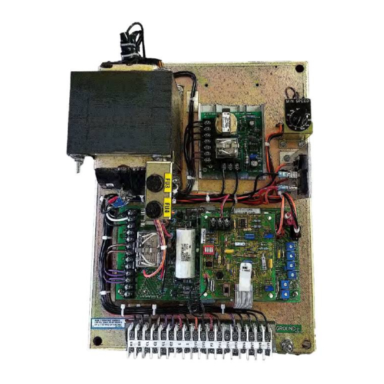
Dynamatic 15-539-14 Instructieblad - Pagina 8
Blader online of download pdf Instructieblad voor {categorie_naam} Dynamatic 15-539-14. Dynamatic 15-539-14 14 pagina's.

maximum value. This limit can be used to prevent the motor breakover torque from being reached during
a condition such as drive output shaft "lock-up" or the period when a large system inertia is being
accelerated. The adjustment range is from 50 to 150% of rated motor torque.
Preliminary Adjustments
Perform the following preliminary adjustments (with no power applied to the controller)
1. Operator Controls (supplied by customer unless specified)
a. Set the Run Speed potentiometer R5 to 0% (Full CCW)
b. Note location of Start and Stop pushbuttons
2.
Main PCB 15-530-5 or 15-530-6
The pots used are screwdriver adjust, single turn pots. Do not use a screwdriver with a blade width
exceeding 1/8 inch.
a. Set the Accel Rate potentiometer R18 to 100% (Full CW)
b. Set the Zero Adjust potentiometer R19 to 0% (Full CCW)
c. Set the Max Speed/Volts potentiometer R21 to 0% (Full CCW)
d. Set the Velocity Damping potentiometer R22 as follows (see trimpot illustration)
e. Set the Time Constant (TC) Adjust potentiometer R26 as follows (see trimpot illustration)
Mechanical Unit*
AC/ACM/ACS/PD/VT
Models EC/AS
Fractional Hp
Fractional Hp
14/121/140
181/182/184/186
18/21/132/160/180/210 50%
214/216/254/256
25/27/180/225/250/280 75%
280/320/360/440
320/360/440
*Typical product number stamped on mechanical unit
nameplate:
A1-100214-0053, Specific mechanical model is AC-214
B2-100210-0008, Specific mechanical model is AS-21
f.
Set the Current Feedback potentiometer
R20 to 0% (Full CCW)
8
Velocity
Damping
0%
75%
Figure: Trimpot Illustration
Mechanical Unit*
AC/ACM/ACS/PD/VT
Models EC/AS
Fractional Hp
FHP/181/182
-
184/186/214
14/18/112/132/140/180
216/254/256/280
21/160/210
320/360/440
25/27/180/225/250/280/
320/360/440
TC
Adjust
0%
15%
30%
100%
