Galak Electronics VG-305B Snelstarthandleiding - Pagina 6
Blader online of download pdf Snelstarthandleiding voor {categorie_naam} Galak Electronics VG-305B. Galak Electronics VG-305B 8 pagina's. Ac traffic light controller
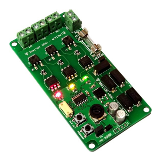
Mode Selection
To select one of the twenty-five modes, first remove
the JP1 jumper (pictured right). Push the PROGRAM
button to cycle through each pattern shown in the
table above. When the button is pressed, the LEDs
will turn on from Red to Yellow to Green and repeat
that pattern. Count the number of times the LEDs
flash to determine the selected sequence. For
example, if mode 5 is selected, the outputs will flash
Red, Yellow, Green and then Red, Yellow to indicate mode 5. Once the desire mode has been
selected, you can replace JP1 to exit the program mode.
Yellow Light Duration
The yellow light duration can be adjusted independently from the main duration control when
one of the standard traffic light modes is selected. Press the button marked "YLW DLY" (pictured
above) to increase the duration by 1 second. Only the yellow LED will flash to indicate the
number of seconds. When 8 seconds has been reached the next button press will revert the
duration back to 3 seconds. Please note that JP1 has no effect on the yellow duration set.
One Touch Program Mode
The One Touch Program mode allows you to switch between programs on the fly without going
through the LED count off. Every time you press the button, the program will immediately
advance to the next program. If the button is pressed with mode 25 active, the program will
revert to mode 1. To use One Touch mode JP1 must be fitted. Once you've selected a mode
that you like, you can connect the outputs to your traffic light.
Connecting to the Outputs
Now that you have verified that the unit is functioning properly, you can
connect up your AC loads. First, make sure the AC power is disconnected
before making any connections. Insert the neutral wire (white) from your RED
light into terminal "1" of CN4 and insert the hot wire (typically red) from your
RED light into terminal "2" of CN4 (denoted with "RED").
Next, Insert the neutral wire (white) from your YELLOW light into terminal "1"
of CN3 and insert the hot wire (typically brown) from your YELLOW light into
terminal "2" of CN3 (denoted with "YELLOW").
Finally, Insert the neutral wire (white) from your GREEN light into terminal "1"
of CN2 and insert the hot wire (typically green) from your GREEN light into
terminal "2" of CN2 (denoted with GREEN). Please note that if only one
neutral wire is available it can be connected to any of the three terminal "1"
connections.