Autonics PMC-2HSP Series Producthandleiding - Pagina 2
Blader online of download pdf Producthandleiding voor {categorie_naam} Autonics PMC-2HSP Series. Autonics PMC-2HSP Series 3 pagina's. 2 axis interpolation type motion controllers
Ook voor Autonics PMC-2HSP Series: Gebruikershandleiding (6 pagina's)
• Keep the distance between power cable and signal cable over 10 cm.
• It is recommended to use twisted pair shield wire when connecting cables to
CN3, 4, 5 connectors.
Ground the shield wires depending on the installation environment.
• It is recommended to use the communication cables provided with the product.
(RS232C, USB)
• When wiring the RS485 cable, twist pair wire is recommended, and use AWG 24 (0.2mm
cable or over.
• This unit may be used in the following environments.
- Indoors (in the environment condition rated in 'Specifications')
- Altitude max. 2,000 m
- Pollution degree 2
- Installation category II
Manual
For proper use of the product, refer to the manuals and be sure to follow the safety
considerations in the manuals.
Download the manuals from the Autonics website.
Software
Download the installation file and the manuals from the Autonics website.
■ atMotion
The program allows to manage the motor driver's parameter setting and monitoring data.
Ordering Information
This is only for reference, the actual product does not support all combinations..
For selecting the specified model, follow the Autonics website.
PMC
-
❶ Communication type
USB: USB / RS232C
485: RS485 / RS232C
Product Components
• Product
• Instruction manual
• Power connector
• I/O connector (P I/F, X axis, Y axis)
Dimensions
• Unit: mm, For the detailed drawings, follow the Autonics website.
35.5
5
2HSP
-
• RS232C comm. cable 1.5 m
• USB comm. cable 1 m (PMC-2HSP-USB Series)
• RS485 comm. connector (PMC-2HSP-485 Series)
64
4
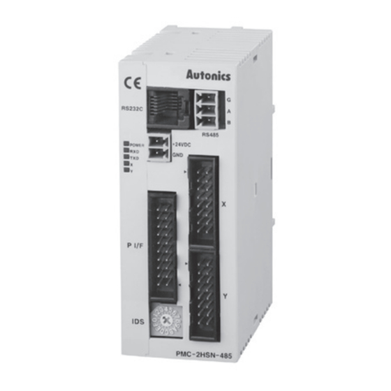
Unit Descriptions
PMC-2HSP-USB
)
2
03
06
02
01
04
05
Connectors
■ CN1: Power connector
Pin Function
1
1
2
2
■ CN3: Parallel I/F connector
❶
20
10
18
17
16
15
14
13
12
11
10
9
8
7
6
5
4
3
2
1
■ CN4, 5: X, Y axis I/O connector
1
2
3
4
5
6
7
8
9
10
11
12
13
14
15
16
■ CN6: RS485 connector
Pin Function Description
3
1
2
2
1
3
■ Connector specifications
• Contact the manufacture for the socket and cable.
Connector
CN3
Parallel I/F connector socket
CN3
I/O cable (sold separately)
CN4, 5 X, Y axis I/O connector socket
01. Power / Status indicator
PMC-2HSP-485
02. Power connector (CN1)
03
06
03. RS232C comm. connector (CN2)
02
01
04. Parallel I/F connector (CN3)
04
05
05. X, Y axis I/O connector (CN4, 5)
07
06. USB / RS485 comm. connector (CN6)
07. ID select rotary switch
■ CN2: RS232C connector
24 VDCᜡ
GND
1
6
Pin Function
I/O
Description
1
RESET
Input Reset
2
HOME
Input Home search start
3
STROBE
Input Drive start
4
X/JOG Y+
Input X axis designate / Jog Y+
5
Y/JOG Y-
Input Y axis designate / Jog Y-
6
STEPSL0/RUN+/JOG X+ Input Step designate 0 / Run+ / Jog X+
7
STEPSL1/RUN-/JOG X-
Input Step designate 1 / Run- / JogX-
Step designate 2 / Drive speed
8
STEPSL2/SPD0
Input
designate 0
Step designate 3 / Drive speed
9
STEPSL3/SPD1
Input
designate 1
10
STEPSL4/JOG
Input Step designate 4 / Jog designate
11
STEPSL5/STOP
Input Step designate 5 / Drive stop
12
MODE0
Input Operation mode designate 0
13
MODE1
Input Operation mode designate 1
14
X DRIVE/END
Output X axis drive / Drive end pulse
15
Y DRIVE/END
Output Y axis drive / Drive end pulse
16
X ERROR
Output X axis error
17
Y ERROR
Output Y axis error
18
GEX
-
GND
19
GEX
-
GND
Sensor power output
20
VEX
-
(24 VDCᜡ, max. 100 mA)
Pin Function
I/O
Description
1
nP+P
Output CW+ drive pulse
2
nP+N
Output CW- drive pulse
3
nP-P
Output CCW+ drive pulse
4
nP-N
Output CCW- drive pulse
5
nOUT0
Output General output 0
6
nOUT1
Output General output 1
7
nIN0
Input General input 0
8
nIN1
Input General input 1
9
nSTOP2
Input Encoder Z phase
10
nSTOP1
Input Home
11
nSTOP0
Input Near Home
12
nLMT+
Input + direction limit
13
nLMT-
Input - direction limit
14
EMG
Input Emergency stop
15
GEX
-
GND
Sensor power output
16
VEX
-
(24 VDCᜡ, max. 100 mA)
B (-)
Transmitting / Receiving data
A (+)
G
Ground when it is required depending on comm. environment.
Specifications
HIF3BA-20D-2.54R
CO20-HP□-L, CO20-HP□-R
HIF3BA-16D-2.54R
Pin Function
1
TXD
2
RXD
3
GND
4
5
N·C
6
Manufacture
Hirose Electric
Autonics
Hirose Electric