Autonics SFC-422 Handmatig - Pagina 2
Blader online of download pdf Handmatig voor {categorie_naam} Autonics SFC-422. Autonics SFC-422 13 pagina's. Safety controllers / safety relay unit
Ook voor Autonics SFC-422: Handmatig (13 pagina's)
Caution
Failure to follow instructions may result in injury or product damage.
01. Use the product within the rated specifications.
Failure to follow this instruction may result in fire or product damage.
02. Use a dry cloth to clean the unit, and do not use water or organic solvent.
Failure to follow this instruction may result in fire.
03. When connecting the power input and relay output, use AWG 18 (0.8mm
or over and tighten the terminal screw model with a tightening torque of 0.3 N m.
Use the copper-conductor wire with the temperature class 60℃.
Failure to follow this instruction may result in fire or malfunction due to contact failure.
04. Keep the product away from metal chip, dust, and wire residue which might flow
into the unit.
Failure to follow this instruction may result in fire, product damage or malfunction.
05. The durability of relay output depends on conditions of relay switching and load.
Be sure to test under actual operating conditions and use it within the appropriate
switching cycles without problem on product performance.
Failure to follow this instruction may result in fire or product damage.
06. Do not touch the relay output terminal immediately after the power source to the
load is disconnected.
Failure to follow this instruction may result in electric shock.
Cautions during Use
• Follow instructions in 'Cautions during Use' . Otherwise, it may cause unexpected accidents.
• The power input is insulated and limited voltage/current or use SELV, Class 2 power supply.
• Connect a protective device (fuse etc.) to the safety output terminal for short-circuit,
overcurrent and ground fault protection.
Failure to follow this instruction may result in fire or malfunction.
• Do not use AC and DC circuits together between safety output terminals.
-SFC-R212: between 13-14 terminal and 23-24 terminal
-SFC-R412, SFC-ER412: between 13-14 terminal and 23-24 terminal or between 33-34 terminal
and 43-44 terminal
-SFC-R212-R2□: between 13-14 terminal and 23-24 terminal or between 37-38 terminal and
47-48 terminal
• Keep away from high voltage lines or power lines to prevent inductive noise. In case installing
power line and input signal line closely, use line filter or varistor at power line and shielded
wire at input signal line. Do not use the product near the equipment which generates strong
magnetic force or high frequency noise.
• Do not drop the product or expose it to excessive vibration or shock. It may cause failure or
malfunction.
• Be sure to turn off the power before connecting, inspecting and repairing the product. It may
cause malfunction or short circuit
• When mounting the products close to each other, the rated current of the relay output is 3A.
Do not apply a current greater than 3A. If the current in the relay output flows 3A, or more,
make sure that the distance between the products should be 20mm or more.
• Assessment of conformity to the required safety level is evaluated for the entire system.
Please consult with a certified certification body regarding the assessment procedure.
• Be sure to set the off-delay time to maintain the safety function of the system. Set the setting
of off-delay switch on both the front and back sides to the same value. If you set it differently,
an error occurs.
• For switches used for safety inputs, logic input and feedback start input, use a switch with
contacts capable of normally switching the micro loads (24 VDCᜡ, 5mA).
• It should be done away regarded as an industrial waste. For more information, please refer to
laws, regulations and standards in the country or region.
• This unit may be used in the following environments.
- Indoors (in the environment condition rated in 'Specifications')
- Altitude max. 2,000m
- Pollution degree 3
- Installation category Ⅲ
Ordering Information
This is only for reference.
For selecting the specific model, follow the Autonics web site.
SFC
-
❶
❷
❸
❶ Function
No mark: Basic unit
A: Advanced unit
N: Non-contact door switch unit
(for Autonics SFN Series)
ER: Expansion relay unit
R: Relay unit
❷ No. of safety instantaneous outputs
Number: Number of outputs
❸ No. of auxiliary outputs
Number: Number of outputs
❹ Off-delay output elements
No mark: P channel FET
R: Relay (Relay unit)
2
2
-
❹
❺
❻
-
❺ No. of Off-delay outputs
No mark: None
2: 2
❻ Max. Off-delay time
Number: Time (unit: sec)
❼ Terminal type
No mark: Screw
L: Screwless
Specifications
Unit
Model
Power supply
Allowable voltage range
Power consumption
01)
) cable
Input
Input time
Cable
Safety output
Instantaneous
Off-delay
04)
Time accuracy
Load current
Leakage current
Operating time
(OFF → ON)
05)
Response (return) time
(ON → OFF)
05)
Auxiliary output
Load current
Leakage current
Logical AND connections
SFN connections
06)
Approval
Certification
Unit weight (package)
01) Not include the power consumption of loads.
(SFC-N exclude the power supplied to the non-contact door switch.)
02) Includes a diagnostic pulse (max. 600 ㎲). Be cautious when using the output
signal as an input signal for the control device.
03) Available changing via setting switch on the back side of the product.
04) Available to set Off-delay time (max. 3 sec. / 300 sec., depends on model)
05) The operation (response) time of each model. The time increases when a logical connection or expansion relay
unit is connected.
06) SFC-N units can only be connected to Autonics non-contact door switch units SFN Series.
Unit
Model
Power supply
Allowable voltage range
Power consumption
01)
Input
Input time
Cable
Safety output
Instantaneous
Off-delay
02)
Time accuracy
Capacity
Life expectancy
Contact resistance
Inductive load switching
Conditional short-circuit
current
Operating time (OFF → ON)
Response (return) time (ON
→ OFF)
04)
Auxiliary output
Load current
Leakage current
Expansion units connections Max. 5 units
❼
Approval
Certification
Unit weight (package)
01) Not include the power consumption of loads.
02) Available to set Off-delay time (max. 3 sec. / 30 sec., depends on model)
03) Use 6 A fast-blow fuse under the IEC 60127 standard as a short-circuit protection device.
04) The operation (response) time of each model. The time increases when a logical connection or expansion relay
unit is connected.
05) Except operation time of advanced unit, non-contact door switch unit
Pollution
Overvoltage category
Impulse withstand
voltag for relay unit
(IEC/EN 60947-5-1)
Dielectric strength
Insulation resistance
Vibration
02)
Vibration (malfunc.)
02)
Shock
02)
Shock (malfunc.)
02)
Protection structure
Ambient temperature
Ambient humidity
01) In case of relay unit, output terminals between 13-14, 23-24 and 33-34, 43-44 (37-38, 47-48)
02) This data based on the product is mounted with bolts. When installing DIN rail, use the product in an
environment with small vibration (condition: less than 0.4 mm double amplitude)
Basic
Advanced
SFC-422-□
SFC-A322-2□-□
24 VDCᜡ
85 to 110% of rated voltage
≤ 2.5 W
≤ 3.0 W
ON: ≥ 11 VDCᜡ ≥ 5 mA, OFF: ≤ 5 VDCᜡ ≤ 1 mA
≥ 50 ms, feedback start (manual) : ≥ 100 ms
≤ 100 m (≤ 100Ω, ≤ 10nF)
P channel FET
02)
4 ×
3 ×
03)
-
2 ×
03)
-
≤ ± 5%
Below 2-point output: ≤ DC 1 A, Over 3-point output: ≤ DC 0.8 A
≤ 0.1 mA
Safety input: ≤ 50 ms
-
Logic input: ≤ 200 ms
-
-
≤ 15 ms, non-contact door switch input or logic input: ≤ 20 ms
2 × PNP transistor: X1, X2 (error)
≤ 100 mA
≤ 0.1 mA
No. of connections: max. 4 units, no. of total connections: max. 20 units
No. of layers: max. 5 layers, cable length: ≤ 100 m
-
-
IEC/EN 61508 (SIL3), IEC/EN 62061 (SILCL3)
IEC/EN 60947-5-1, EN ISO 13849-1 (Category 4, PLe)
UL listed E249635
ᜪ
ᜢ ᜩ ᜦ
≈ 70 g (≈ 120 g)
≈ 90 g (≈ 140 g)
Expansion relay
Relay
SFC-ER412-□
SFC-R412-□
24 VDCᜡ
85 to 110% of rated voltage
≤ 2.5 W
≤ 4.0 W
ON: ≥ 11 VDCᜡ ≥ 5 mA, OFF: ≤ 5 VDCᜡ ≤ 1 mA
≥ 50 ms, feedback start (manual) : ≥ 100 ms
≤ 100 m (≤ 100Ω, ≤ 10nF)
Relay (A contact)
Relay (A contact)
4 ×
4 ×
-
-
-
-
240 VACᜠ 5 A resistance load, 30 VDCᜡ 5 A resistance load
Mechanical: ≥ 10,000,000 operations,
Malfunction: ≥ 50,000 operations
≤ 100 mΩ
IEC60947-5-1: AC-15(230 V/2 A), DC-13(24 V/1.5 A), UL508: B300/R300
100 A
03)
≤ 30 ms
≤ 100 ms
04)
05)
≤ 10 ms
≤ 15 ms
1 × PNP transistor:
1 × PNP transistor: X1
X2 (error)
≤ 100 mA
≤ 100 mA
≤ 0.1 mA
-
IEC/EN 61508 (SIL3), IEC/EN 62061 (SILCL3)
IEC/EN 60947-5-1, EN ISO 13849-1 (Category 4, PLe)
UL listed E249635
ᜪ
ᜢ ᜦ
ᜢ ᜩ ᜦ
≈ 100 g (≈ 150 g)
≈ 110 g (≈ 160 g)
3
III
Input terminals and relay output terminals: 6 kV
Relay contacts between 13-14 / 23-24 and 33-34 / 43-44 (37-38 / 47-48): 6 kV
between 13-14 and 23-24: 4 kV
between 33-34 and 43-44 (37-38 and 47-48): 4 kV
Basic / Advanced / Non-contact door switch unit:
500 VACᜠ 50/60 Hz for 1 min. (between all terminals and case)
Expansion relay / relay unit:
1,500 VACᜠ 50/60 Hz for 1 min. (between all terminals and case)
2,500VACᜠ 50/60Hz for 1 min. (between input terminals and output
terminals
)
01)
≥ 100 MΩ (500 VDCᜡ megger)
0.75 mm amplitude at frequency of 10 to 55 Hz (for 1 min) in each X, Y, Z
direction for 1 hour
0.5 mm amplitude at frequency of 10 to 55 Hz (for 1 min) in each X, Y, Z
direction for 10 minutes
300 m/s
(≈ 30 G) in each X, Y, Z direction for 3 times
2
100 m/s
(≈ 10 G) in each X, Y, Z direction for 3 times
2
IP20
-10 to 55 ℃, storage: -25 to 65 ℃ (rated at no freezing or condensation)
25 to 85 %RH, storage: 25 to 85 %RH (rated at no freezing or condensation)
Non-contact door switch
SFC-N322-2□-□
≤ 3.5 W
3 ×
03)
2 ×
03)
≤ ± 5%
Non-contact door switch
input: ≤ 100 ms
Max. 30 units
≈ 100 g (≈ 150 g)
≈ 50 ms
P-CH FET
safety output
Max. 600 ㎲
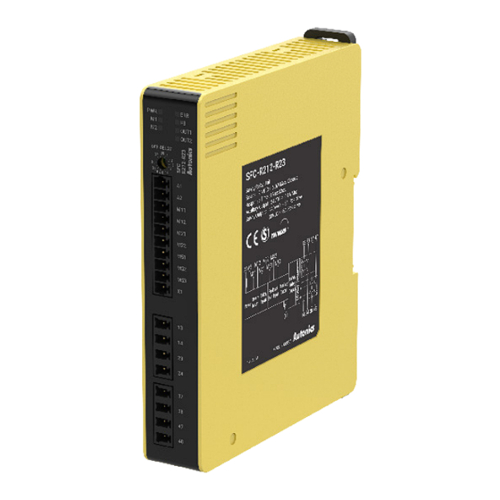
SFC-R212-□
SFC-R212-R2□-□
≤ 4.0 W
≤ 6.0 W
2 ×
2 ×
2 ×
≤ ± 5%
≈ 80 g (≈ 130 g)
≈ 110 g (≈ 150 g)