Autonics SFC-A322-2 Handmatig - Pagina 3
Blader online of download pdf Handmatig voor {categorie_naam} Autonics SFC-A322-2. Autonics SFC-A322-2 13 pagina's. Safety controllers / safety relay unit
Ook voor Autonics SFC-A322-2: Handmatig (13 pagina's)
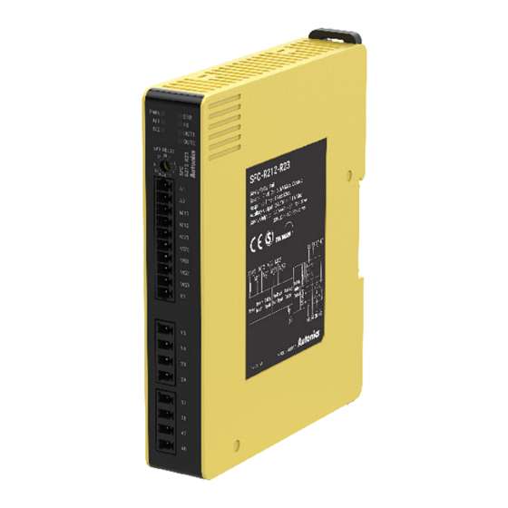
Parts Descriptions
Front
Back
06
01
04
02
04
05
03
06
07
08
Expansion
relay unit
Indicators
Indicators
Model SFC
PWR (green) Power
●
M1 (white)
Safety input 1 ●
M2 (white)
Safety input 2 ●
Non-contact
NS (white)
door switch
ㅡ
input
AND (white) Logic input
ㅡ
ERR (red)
Error
●
Feedback
FB (white)
●
start input
OUT1
Instantaneous
●
(green)
safety output
OUT2
Off-delay
ㅡ
(green)
safety output
Setting Switches
■ Setting Switch for off-delay time
• Only off-delay output model
• Available to set off-delay time (max. 3 / 300 / 30 sec., depends on model)
• The settings of the switch on the front and back of the product must be the same.
Other settings are displayed as an error.
• If the off-delay time is set as 0 (factory default), the product operates as the
instantaneous output.
Max. 3 sec.
SFC-A322-23-□
Model
SFC-N322-23-□
SFC-R212-R23-□
0/0.2/0.3/0.4/0.5/0.6/0.
Total 16
7/0.8/0.9/1.0/1.2/1.4/1.
level
8/2.0/2.5/3.0 sec.
■ Setting switch for function
• Only advanced / Non-contact door switch unit.
• The setting of switches for each function must meet each other. Other settings are
displayed as an error
Function
SW1
SW2
OFF
OFF
Logic (AND) input
ON
ON
Function
SW3
SW4
OFF
OFF
Off-delay safety
output points
ON
ON
01. Indicators
02. Power supply, I/O signal terminals
03. Safety output (P ch FET or relay)
terminals
04. Setting switch for off-delay time
(only off-delay output model)
The settings of the switch on the front and
back of the product must be the same. Other
settings are displayed as an error.
05. Setting switch for function
(only advanced / non-contact door switch
unit)
The setting of switches for each function
must meet each other. Other settings are
displayed as an error.
06. Rail Lock
07. Loop connector
(only advanced / non-contact door switch
unit)
Do not disconnect the loop connector
when using a single unit. When connecting
the expansion relay unit, insert the loop
connector to the loop port of a unit, which
located at the end position (farthest to the
right). If the loop connector is not inserted,
FB error occurs.
08. Expansion connector
When connecting the expansion relay unit,
remove the loop connector on the top of
the controller and insert the expansion
connector.
SFC-R□12
SFC-A
SFC-N
SFC-ER
-□
●
●
●
●
●
●
ㅡ
●
●
●
ㅡ
●
ㅡ
●
ㅡ
ㅡ
●
●
ㅡ
ㅡ
●
●
●
●
●
●
ㅡ
●
●
●
●
●
●
●
ㅡ
ㅡ
Max. 300 sec.
Max. 30 sec.
SFC-A322-2300-□
SFC-R212-R230-□
SFC-N322-2300-□
0/10/20/30/40/50/60/7
0/1/2/4/5/6/7/8/9/10/
0/80/90/100/120/150/
12/14/16/20/25/30 sec.
180/240/300 sec.
Logic (AND)
input
Not available
Available
Instantaneous
Off-delay safety
safety output
output
S14, S24, S34
S44, S54
S14
S24, S34, S44, S54
Dimensions
• Unit: mm, For the detailed drawings, follow the Autonics web site.
• The below is based on SFC-A (screw type) model
Mounting
with bolts
Model
Basic unit
Advanced unit
Non-contact door
switch unit
Expansion relay unit
Relay unit
Installation
■ Mounting with bolts
1. Pull each rail locks to up and down.
(attach/detach: ≥ 25N)
2. Insert bolts and fix it on rail lock.
(fixing torque: 1.0 N m to 1.5 N m)
■ Mounting on DIN Rail
SFC-R212
1. Hang the top rail lock to DIN rail.
-R2□-□
2. Push and press the module to down direction.
●
●
3. Install END PLATE at both ends of the module to fix the products.
●
(It is the same way when using one unit.)
■ Removing on DIN Rail
ㅡ
1. Insert a screwdriver into the rail hook of the lower rail lock.
2. Lift the screwdriver and pull the lower rail lock downward.
ㅡ
●
3. Lift the module with the lower rail lock pulled down.
●
●
●
■ How to connect the expansion relay units (SFC-ER412-□)
In case of advanced unit and non-contact door switch unit, it is possible to increase the
number of safety outputs of relay type by connecting expansion relay unit (SFC-ER412-
□). (Up to 5 expansion relay units can be connected to each controller)
When the safety output of the controller is on, the output of the expansion relay unit
also goes to on.
The controller is installed from the end of the left or right side.
Power of expansion relay unit should be supplied individually.
E.g.) Installation from the end of left side
1. Install the expansion relay units (max. 5 units) toward the right side based on the
controller.
2. Remove the loop connector on the top of the controller.
3. Connect the expansion connector of each right (expansion relay unit) to the
expansion connector of the left unit.
4. Insert the loop connector removed in 2 into the loop port of the unit, which located at
the end position (farthest to the right).
SFC-A
SFC-N
B
A
C
Mounting on
DIN rail
A
B
SFC-422-□
22.5
18.3
SFC-A322-□-□
35
18.3
SFC-N322-□-□
35
18.3
SFC-ER412-□
22.5
18.3
SFC-R412-□
22.5
18.3
SFC-R212-□
17.5
13.3
SFC-R212-R□-□
22.5
18.3
+
Loop connector
1
2
3
4
5
SFC-ER
Panel cut-out
2-M4
C
Screw type: 15.3
Screwless type: 15.5